Bender CMD420 Manual
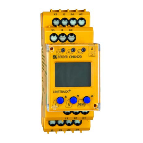
Current monitoring device for monitoring of 3ac current with current transformer for overcurrent or undercurrent or in window mode for overcurrent and under current
Hide thumbs
Also See for CMD420:
- Quick start manual (9 pages) ,
- Installation bulletin / reference manual (2 pages) ,
- Manual (56 pages)
Table of Contents
Advertisement
Quick Links
Advertisement
Table of Contents

Related Manuals for Bender CMD420


Summary of Contents for Bender CMD420
- Page 1 Manual CMD420/421 Current monitoring device for monitoring of 3AC current with current transformer for overcurrent or undercurrent or in window mode for overcurrent and under current Software version CMD420: D287 V1.1x Software version CMD421: D294 V1.1x CMD42x_D00101_01_M_XXEN/10.2021...
- Page 2 Bender GmbH & Co. KG Postfach 1161 • 35301 Grünberg • Germany Londorfer Str. 65 • 35305 Grünberg • Germany Tel.: +49 6401 807-0 • Fax: +49 6401 807-259 E-Mail: info@bender.de • www.bender.de © Bender GmbH & Co. KG All rights reserved.
-
Page 3: Table Of Contents
Table of Contents 1. Important information ....................5 How to use this manual ....................5 Technical support: service and support ..............5 Training courses ....................... 6 Delivery conditions, warranty and liability ............. 7 Inspection, transport and storage ................7 Warranty and liability ..................... 7 Disposal .......................... - Page 4 Inhaltsverzeichnis 5. Operation and configuration .................. 19 Display elements in use ....................19 Function of the operating elements ..............20 Menu structure ......................21 Display in standard mode ..................22 Display in menu mode ....................23 5.5.1 Parameter query and setting: overview ............23 5.5.2 Changeover from overcurrent to undercurrent mode or to window mode ....................
-
Page 5: How To Use This Manual
CMD42x_D00101_01_M_XXEN/10.2021... -
Page 6: Important Information
**Mo-Thu 7.00 a.m. - 8.00 p.m., Fr 7.00 a.m. - 13.00 p.m 1.3 Training courses Bender provides training on how to use the universal measuring device. Current dates of training courses and workshops can be found on the Internet at http://www.bender.de ->... -
Page 7: Delivery Conditions, Warranty And Liability
ZVEI (Zentralverband Elektrotechnik- und Elektronikindustrie e.V., - German Electrical and Electronic Manufacturers' Association) also applies. Conditions of sale and delivery can be obtained from Bender in printed or electronic format. 1.5 Inspection, transport and storage Inspect the dispatch and equipment packaging for damage, and compare the con- tents of the package with the delivery documents. -
Page 8: Disposal
13th August 2005 must be taken back by the manufacturer and disposed of properly. For more information on the disposal of Bender devices, refer to our website at www.bender.de -> Service & support... -
Page 9: Safety Instructions
2.3 Intended use The current monitoring device CMD420 resp. CMD421 monitors a three-phase system and also three different AC systems for undercurrent or overcurrent, and in window mode for undercurrent and overcurrent. For current measurement, three external standard current transformers are to be connected according to the wiring diagram. - Page 10 Safety instructions CMD42x_D00101_01_M_XXEN/10.2021...
-
Page 11: Function
Undercurrent and overcurrent monitoring in AC systems, current monitoring with window discriminator function • Current monitoring using standard current transformers: x/ 1A (CMD420), x/ 5A (CMD421) • Two separately adjustable alarm relays with one changeover contact each (K1, K2) •... -
Page 12: Automatic Self Test
3.2.4 Malfunction In the event of an internal malfunction, all three LEDs will flash. The error code (E01…E32) will appear on the display. In such a case please contact the Bender Service. 3.2.5 Fault memory The fault memory can be activated, deactivated or set to continuous mode (con). If the fault memory is set to "con“... -
Page 13: Assigning Alarm Categories To Alarm Relays K1/K2
CAUTION alarm category "Err" has to be assigned to the selected alarm relay in the menu out/r1 or r2. If these conditions cannot be met, periodic inspection of the CMD420/CMD421 is required! 3.2.9 Delay times , The times t, t and t described below, delay the output of alarms via LEDs and relays. -
Page 14: Transformation Ratio Of The Current Transformers
The transformation ratio for the current transformers has to be set as factor n in the menu "Set". The CMD420 requires current transformers with a transformation ratio of n = x/1A. The CMD421 requires current transformers with a transformation ratio of n = x/5A. -
Page 15: Installation, Connection And Commissioning
4. Installation, connection and commissioning Only qualified personnel are permitted to carry out the work nec- essary to install, commission and run a device or system. Risk of electrocution due to electric shock! Touching live parts of the system carries the risk of: •... -
Page 16: Connection Of The Device
Installation, connection and commissioning 4.2 Connection of the device Connect the device according the wiring diagram. ~/– IT-System l1 k2 Connect the conductor to the push- wire terminals according to the schematic diagram. Terminal Connections Connection to supply volt- A1, A2 age U k1, l1 Connection to the conduc-... -
Page 17: Commissioning
Response value overcurrent I2 (alarm) 0.30 A CMD421 Response value overcurrent I1 (prewarning) 0.75 A (50 % of I2) Response value overcurrent I2 (alarm) 1.50 A CMD420 / CMD421 Hysteresis: 15 % Fault memory M: activated (on) Operating mode K1/K2 N/C operation (n.c.) -
Page 18: Maintenance
Installation, connection and commissioning 4.5 Maintenance One alarm relay of the CMD420 CMD421 must work in N/C opera- tion with the alarm category "Err" assigned to this relay, otherwise periodic inspection will be necessary! CAUTION A functional test is recommended to be carried out at regular intervals. It is preferable to check correct alarm indication by means of a current fault. -
Page 19: Operation And Configuration
5. Operation and configuration 5.1 Operating elements Device front Element Mode Power On LED, green LED Alarm 1 lit up (yellow): Response value 1 reached LED Alarm 2 lit up (yellow): Response value 2 reached Up button (< 1.5 s): Menu items/values Test button (>... -
Page 20: Function Of The Operating Elements
Operation and configuration 5.2 Display elements in use Display elements in use Element Mode Values of the measurement inputs k1/l1, L1, L2, L3 k2/l2, k3/l3 Reload function with memory = off (L = I.) Transformation ratio for external current transformer <... -
Page 21: Menu Structure
Operation and configuration 5.3 Menu structure All adjustable parameters are listed in the columns "Menu" and "Adjustable parameters". A display-like representation is used to illustrate the parameters in the column Menus. Different alarm categories can be assigned to the alarm relays K1, K2 via the submenus r1, r2. This is done by activation or deactivation of the respective function. -
Page 22: Display In Standard Mode
Operation and configuration 5.4 Display in standard mode By default, the currently measured current of measuring channel L1 is displayed. By pressing the Down button the following values can be queried consecutively: – Current of measuring channel L2 – Current of measuring channel L3 –... -
Page 23: Display In Menu Mode
Operation and configuration 5.5 Display in menu mode 5.5.1 Parameter query and setting: overview Menu item Adjustable parameter Response value query and setting: – Alarm I2 (AL2), (undercurrent, overcurrent or window function can be set in the SEt/I menu) – Prewarning I1 (AL1), (X % of I2) –... - Page 24 Operation and configuration Menu structure t >1,5 s t > 1,5 s t < 1,5 s t < 1,5 s t > 1,5 s Parameter settings An example is given below on how to change the alarm response value for overcurrent > I1.
-
Page 25: Changeover From Overcurrent To Undercurrent Mode Or To Window Mode
Operation and configuration 5. Use the Up or Down button to set the appropriate prewarning value. Confirm with Enter. I1 flashes. 6. You can exit the menu by: – pressing the Enter button for more than 1.5 seconds to reach the next higher level or –... -
Page 26: Response Value Setting For Overcurrent
Operation and configuration 5.5.3 Response value setting for overcurrent: - Response value I2 (overcurrent) - Response value I1 (overcurrent) - Hysteresis (Hys) of the response values I1, I2 Increasing the response value I2 (Example: overcurrent) Increasing the response value I1 (prewarning overcurrent) Setting the hysteresis of the response value CMD42x_D00101_01_M_XXEN/10.2021... -
Page 27: Setting The Fault Memory And Alarm Relay Operating Mode
Operation and configuration 5.5.4 Setting the fault memory and alarm relay operating mode Setting the fault memory to con mode Setting the alarm relay K1 to N/O operation (n.o.) Setting the number of reload cycles >1,5 s CMD42x_D00101_01_M_XXEN/10.2021... -
Page 28: Assigning Alarm Categories To The Alarm Relays
Operation and configuration 5.5.5 Assigning alarm categories to the alarm relays Overcurrent, undercurrent and device-related errors of the current monitor can be as- signed to the alarm relays K1 (r1, 1) and K2 (r2, 2). By default, the alarm relays K1 and K2 sig- nal prewarning and alarm in case of overcurrent. -
Page 29: Setting Time Delays
Operation and configuration Alarm relay K1: Activating the category response value I2 >1,5 s Alarm relay K1: Deactivating the category device test >1,5 s Deactivating an alarm relay (K1/K2) via the menu prevents an alarm being indicated by the respective changeover contact! An alarm will be signalled by the respective alarm LED (AL1/AL2) CAUTION only! -
Page 30: Changing From Overcurrent Operation To Window Operation
Operation and configuration The control steps for setting the response delay t and the start-up delay t are shown as an example. Setting the response delay >1,5 s Setting the start-up delay >1,5 s 5.5.7 Changing from overcurrent operation to window operation Use this menu item to set whether the response values of the device apply to overcurrent (HI) or undercurrent operation (Lo). -
Page 31: Setting The Transformation Ratio For External Current Transformer
Operation and configuration 5.5.8 Setting the transformation ratio for external current transformer >1,5 s 5.5.9 Factory setting and password protection This menu can be used to activate password protection, to modify the password or to de- activate password protection. It is also where the device can be reset to the factory settings. a) Activating the password protection >1,5 s CMD42x_D00101_01_M_XXEN/10.2021... -
Page 32: Restore Factory Setting
Operation and configuration b) Change password >1,5 s c) Deactivate password protection >1,5 s 5.5.10 Restore factory setting ..CMD42x_D00101_01_M_XXEN/10.2021... -
Page 33: Device Information Query
Operation and configuration 5.5.11 Device information query This function is used to query the software version (1.xx). After activating this function, data will be displayed as a scrolling text. Once one pass is completed you can select individual data sections using the Up/Down buttons.. - Page 34 Operation and configuration CMD42x_D00101_01_M_XXEN/10.2021...
-
Page 35: Technical Data
............................AC / DC 70…300 V Frequency range U ..............................15…460 Hz Power consumption .................................≤ 4 VA Measuring circuit CMD420 Nominal measuring range (r.m.s. value) n = 1 ....................... AC 0…1 A Overload capability, continuous............................. 2 A Overload capability < 5 s ................................5 A Load per measuring input .............................. - Page 36 Technical data Response values CMD420 Undercurrent Lo < I (Alarm 2) n = 1......................AC 0.1…1 A (0.3 A)* Undercurrent Lo < I (Alarm 1) n = 1....................100…200 % (150 %)* ....................Take a maximum nominal current of 1 A into consideration! Overcurrent Hi >...
- Page 37 Displays, memory Display........................LC display, multifunctional, not illuminated Display range, measured value (r.m.s. value) x transformation ratio n..........CMD420: AC 0…1 A x n ................................CMD421: AC 0…5 A x n Relative uncertainty in the range of 42…460 Hz................... ±5 %, ±2 digits Measured-value memory (HiS) for the first alarm value ............
- Page 38 Degree of protection, terminals (DIN EN 60529)........................IP20 Enclosure material..............................polycarbonate Flammability class................................ UL94 V-0 DIN rail mounting acc. to..............................IEC 60715 Screw fixing ............................. 2 x M4 with mounting clip Software version CMD420............................D287 V1.1x Software version CMD421............................D294 V1.1x Weight .....................................≤ 150 g CMD42x_D00101_01_M_XXEN/10.2021...
-
Page 39: Standards, Approvals And Certifications
There will only be a label in this field, if the device is different from the standard version. 6.4 Ordering details Supply voltage U Device type Response value Art. No. CMD420-D-1 AC 16…72 V / DC 9.6 V…94 V 0.1…1 A x n B73060006 (push-wire terminals) DC15…460 Hz AC 16…72 V/ DC 9.6 V…94 V... -
Page 40: Revision History
Technical data 6.5 Revision history Document- Valid from Date State/Changes version software Editorial revision New design with format change from DIN A6 to DIN A5 10.2021 S. 38 Update of the climate classes according to EN IEC 60721-3-4:2019 S. 40 Revision history CMD42x_D00101_01_M_XXEN/10.2021... - Page 41 INDEX the alarm relays 28 - Changeover from overcurrent Adjustable parameters, list 21 LED Alarm 1 lights 20 operation to window opera- Automatic self test 12 LED Alarm 2 lights 20 tion 30 - Response value setting 26 Delay on release toff 13 Malfunction 12 - Setting time delays 29 Deleting the fault alarms 20...
- Page 42 CMD42x_D00101_01_M_XXEN/10.2021...
- Page 44 Bender GmbH & Co. KG P.O. Box 1161 • 35301 Grünberg • Germany Londorfer Str. 65 • 35305 Grünberg • Germany Tel.: +49 6401 807-0 • Fax: +49 6401 807-259 E-Mail: info@bender.de • www.bender.de © Bender GmbH & Co. KG All rights reserved.
Need help?
Do you have a question about the CMD420 and is the answer not in the manual?
Questions and answers