Table of Contents
Advertisement
Quick Links
Advertisement
Table of Contents

Related Manuals for Growatt SPF 3000T HVM-G2


Summary of Contents for Growatt SPF 3000T HVM-G2
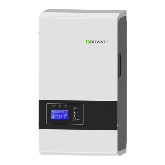
- Page 1 User Manual Off Grid Solar Inverter SPF 3000T HVM-G2 Version: 1.0...
-
Page 2: Table Of Contents
Table Of Contents Information on this Manual ................................1 Validity ......................................1 Scope ....................................... 1 Target Group ....................................1 Safety Instructions ..................................1 Introduction ......................................2 Features ......................................2 Product Overview ..................................3 Installation ......................................4 Unpacking and Inspection ................................4 Mounting the Unit .................................. -
Page 3: Information On This Manual
Information on this Manual Validity This manual is valid for the following devices: SPF 3000T HVM-G2 Scope This manual describes the assembly, installation, operation and troubleshooting of this unit. Please read this manual carefully before installations and operations. Target Group This document is intended for qualified persons and end users. -
Page 4: Introduction
Introduction Hybrid Power System This is a multifunctional off grid solar inverter, integrated with a MPPT solar charge controller, a low frequency pure sine wave inverter and a UPS function module in one machine, which is perfect for off grid backup power and self-consumption applications. -
Page 5: Product Overview
Product Overview 1. LCD display 2. Status indicator 3. Charging indicator 4. Fault indicator 5. Function buttons 6. RS485 communication Port 7. BMS communication Port 8. PV input 9. Current sharing ports 10. Parallel communication ports 11. AC output 1 12. -
Page 6: Installation
Installation Unpacking and Inspection Before installation, please inspect the unit. Be sure that nothing inside the package is damaged. You should have received the following items in the package: The unit x 1 User manual x 1 Communication cable x 1 Software CD x 1 Screws x 3 Mounting board x 1... -
Page 7: Battery Connection
Recommended battery cable and terminal size: Torque value Model Wire Size SPF 3000T HVM-G2 1 * 4 AWG 2-3 Nm Note: For lead acid battery, the recommended charge current is 0.2C(Cbattery capacity) Please follow below steps to implement battery connection: 1. - Page 8 Program 51, which is to set the protocol type. There are several protocols in the inverter. Please get instruction from Growatt to choose which protocol to match the BMS. 1. Connect the end of RJ45 of battery to BMS communication port of inverter...
- Page 9 LCD setting To connect battery BMS, need to set the battery type as “LI” in Program 05. After set “LI” in Program 05, it will switch to Program 51 to choose communication protocol. You can choose RS485 communication protocol which is from L01 to L50, and you can also choose CAN communication protocol which is from L51 to L99.
-
Page 10: Ac Input/Output Connection
Default 20%, 5%~49% Settable,value set lower than this program can be set up Program 12 setting Note: Any questions about communicating with BMS, please consult with Growatt. AC Input/Output Connection CAUTION!! Before connecting to AC input power source, please install a separate AC breaker between inverter and AC input power source. - Page 11 WARNING: Be sure that AC power source is disconnected before attempting to hardwire it to the unit. 4. Then, insert AC output wires according to polarities indicated on terminal block and tighten terminal screws. Be sure to connect PE protective conductor first.
-
Page 12: Pv Connection
To reduce risk of injury, please use the proper recommended cable size as below. Torque value Model Wire Size SPF 3000T HVM-G2 1 * 8AWG 1.2-1.6 Nm PV Module Selection: When selecting proper PV modules, please be sure to consider below parameters: 1. -
Page 13: Communication Connection
Communication Connection Please use supplied communication cable to connect to inverter and PC. Insert bundled CD into a computer and follow on-screen instruction to install the monitoring software. For the detailed software operation, please check user manual of software inside of CD. Dry Contact Signal There is one dry contact(3A/250VAC) available on the rear panel. -
Page 14: Battery Charger
Battery Charger The inverter is equipped with an active PFC (power factor correction) multistage battery charger. When AC voltage is in the range of 154~260VAC, the charging current is 100%. The inverter is with a strong charging current, and the charge current can be adjusted from 10A~40A. There are mainly 3 stages: Bulk Charging: This is the initial stage of charging. -
Page 15: Battery Equalization
Battery Equalization Equalization function is added into charge controller. It reverses the buildup of negative chemical effects like stratification, a condition where acid concentration is greater at the bottom of the battery than at the top. Equalizationalso helps to remove sulfate crystals that might have built up on the plates. If left unchecked, this condition, called sulfation, will reduce the overall capacity of the battery. -
Page 16: Operation
Operation Power ON/OFF Once the unit has been properly installed and the batteries are connected well, simply press On/Off switch (located on the button of the case) to turn on the unit. The switch is located on the underside to the bottom right of the product. - Page 17 LCD Display Icons Icon Description AC Input Information AC input icon Indicate AC input power, AC input voltage, AC input frequency, AC input current Indicate AC power loads in bypass PV Input Information PV input icon Indicate PV power, PV voltage, PV current Output Information Inverter icon Indicate...
- Page 18 In AC mode, battery icon will present Battery Charging Status Status Battery voltage LCD Display <2V/cell 4 bars will flash in turns. Bottom bar will be on and the other three bars Constant Current 2 ~ 2.083V/cell will flash in turns. mode / Constant Bottom two bars will be on and the other two bars 2.083 ~ 2.167V/cell...
- Page 19 LCD Setting After pressing and holding ENTER button for 3 seconds, the unit will enter setting mode. Press “UP” or “DOWN” button to select setting programs. Then press “ENTER” button to confirm the selection or ESC button to exit. Program Description Setting Option Solar first...
- Page 20 AGM (default) Flooded Lithium (only suitable when communicated with BMS) User-Defined Battery type If “User-Defined” is selected, battery charge voltage and low DC cut-off voltage can be set up in program 19, 20 and 21. User-Defined 2 (suitable when lithium battery without BMS communication) If “User-Defined 2”...
- Page 21 Default 46.0V, 44.0V~51.2V Settable Setting voltage point back to utility source when selecting “SBU priority” or “Solar first” in program 01 Default 40%, 6%~50% Settable, value set higher than Program 21 setting Setting voltage point back Default 54.0V, 48.0V~58.0V Settable to battery mode when selecting “SBU priority”...
- Page 22 Default 42.0V, 40.0V~48.0V Settable Low DC cut-off voltage. If self-defined is selected in Default 20%, 5%~49% Settable,value set lower than Program 12 setting program 5, this program can When reach Low DC cut-off voltage: be set up. If battery power is only power source available, inverter will shut down. If PV energy and battery power are available, inverter will charge battery without AC output.
-
Page 23: Display Information
Display Information The LCD display information will be switched in turns by pressing “UP” or “DOWN” key. The selectable information is switched as below order: voltage, frequency, current, power, firmware version. Setting Information LCD display ① AC Input voltage ② Output voltage ③... -
Page 24: Operating Mode Description
Operating Mode Description Operation mode Description LCD display When utility grid connected, no charging; Standby mode No output is PV can charge Note: *Standby mode: The supplied by the inverter is not turned on yet but unit but PV it at this time, the inverter can still can charge charge battery without AC... -
Page 25: Fault Code
Fault Code Fault Code Fault Event Icon on Inverter Fan is not working Inverter Over temperature Battery voltage is too high Battery voltage is too low Output short circuited Output voltage is abnormal. Output voltage is too high. Overload time out BMS communication error Over current or surge Warning Code... -
Page 26: Trouble Shooting
Trouble Shooting Problem LCD/LED/Buzzer Explanation / Possible cause What to do Unit shuts down LCD/LEDs and buzzer automatically will be active for 3 1. Re-charge battery. The battery voltage is too low during startup 2. Replace battery. (<1.91V/Cell) seconds and then process. -
Page 27: Specifications
Specifications Table 1 Line Mode Specifications INVERTER MODEL SPF 3000T HVM-G2 Input Voltage Waveform Pure sine wave/ same as input (bypass mode) Nominal Input Voltage 230Vac Input voltage range 184~272Vac(UPS);154~272Vac(APL) Low Loss Voltage 184Vac±7V(UPS); 154Vac±7V(APL) Low Loss Return Voltage 194Vac±7V(UPS); 164Vac±7V(APL) High Loss Voltage >272Vac±7V... - Page 28 Table 2 Inverter Mode Specifications INVERTER MODEL SPF 3000T HVM-G2 Rated Output Power 3KVA / 3KW Output Voltage Waveform Pure Sine Wave Output Voltage Regulation 230Vac±5% Output Frequency 50Hz Peak Efficiency Overload Protection 10s@101%~150% load; 5s@≥150% load Surge Capacity 9KVA / 9KW...
- Page 29 Table 3 Charge Mode Specifications Utility Charging Mode INVERTER MODEL SPF 3000T HVM-G2 Charging Algorithm 3-Step Max. AC Charging Current 40Amp(@V =230Vac) Bulk Charging Flooded Battery 58.4Vdc Voltage AGM / Gel Battery 56.4Vdc Floating Charging Voltage 54Vdc MPPT Solar Charging Mode Max.
Need help?
Do you have a question about the SPF 3000T HVM-G2 and is the answer not in the manual?
Questions and answers