Table of Contents
Advertisement
Quick Links
Advertisement
Table of Contents

Related Manuals for dymax BlueWave FX-1250


Summary of Contents for dymax BlueWave FX-1250
- Page 1 BlueWave FX-1250 ® Large-Area LED Flood System User Guide...
- Page 2 Please note that most dispensing and curing system applications are unique. Dymax does not warrant the fitness of the product for the intended application. Any warranty applicable to the product, its application, and use is strictly limited to that contained in the Dymax standard Conditions of Sale.
-
Page 3: Table Of Contents
Contents Introduction ................. 4 Where to Get Help ................... 4 Safety ................... 4 Product Overview ............... 5 Controller Main Components ................. 6 Unpacking ................... 8 Unpacking and Inspecting Your Shipment........... 8 Parts Included ....................8 System Installation ..............9 System Assembly .................... 9 System Cooling.................... -
Page 4: Introduction
8:00 a.m. to 5:30 p.m. Eastern Standard Time. You can also email Dymax at info@dymax.com. Contact information for additional Dymax locations can be found on the back cover of this user guide. Additional resources are available to ensure a trouble-free experience with our products: •... -
Page 5: Product Overview
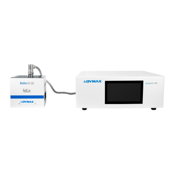
BlueWave FX-1250 VisiCure The BlueWave FX-1250 functions as a flood-curing system with a 127 mm x 127 mm (5 in x 5 in) irradiated curing area. The unit can be operated in admin mode (unrestricted control) or production mode (restricted control) which allows for process management via access restrictions. -
Page 6: Controller Main Components
Controller Main Components The interactive parts of the controller include the Display Screen, Power Switch, Power Input Receptacle, Output CH1 ,Output CH2 , RS232 Receptacle, RS485 Receptacle and PLC Interface. Figure 2. Controller Front Panel Display Screen Figure 3. Controller Back Panel RS232 Receptacle Output CH1 PLC Interface... - Page 7 Table 1. Labels Warning Labels Product Information Label High Temperature Caution Label Emitter Wavelength Label (RediCure, PrimeCure, or VisiCure) U S E R G U I D E B L U E W A V E ® F X - 1 2 5 0...
-
Page 8: Unpacking
Upon arrival, inspect all boxes for damage and notify the shipper of box damage immediately. Open each box and check for equipment damage. If parts are damaged, notify the shipper and submit a claim for the damaged parts. Contact Dymax so that new parts can be shipped to you immediately. -
Page 9: System Installation
System Cooling The system can be used in various scenarios with additional mounting fixtures or Dymax accessories, i.e., as a bench-top unit with a stand on a chamber, as part of a conveyor, etc. This system should only be operated in a location that provides proper cooling. -
Page 10: Wiring And Connections
Power Switch: Turns the unit on and off. Power Input: The power cord plugs in here. Only use the power cord supplied by Dymax (Figure 9) as the power cord supplied with the controller is specifically designed and certified to work with the controller. -
Page 11: Connections
Connections The connection cable has two 15P plugs that connect the controller to the emitter. Plugging the connection cable into the controller: Roll the plug clockwise while inserting to plug the cable in. Roll the plug counterclockwise while removing to unplug the cable (Figure 11). Plugging the connection cable into the emitter: Roll the plug clockwise while inserting to plug the cable in. -
Page 12: I/O Interface Summary
0,16,18 (1) PLC power channel is a 24V source available for use to drive PLC logic but must be current limited using pull-down resistors to protect the BlueWave FX-1250 when directly attached to the I/O channels through the PLC connector. -
Page 13: Plc Uv Control
PLC UV Control PLC switching may be driven by manual switch, relay, or optical coupler. Only analog intensity uses a voltage input to the PLC. To use the PLC mode, the PLC ENABLE (input pin 1) must be pulled down to low by grounding to the COM ground point The PLC INTERLOCK (input Pin 11) disables all the UV output when it is de-asserted. -
Page 14: Status Output
Status Output Figure 15. There are three status outputs. They are driven by an optical Status Outputs Connection Using On-Board 24V Source coupler. These outputs work in any mode and can be used as status inputs for PLC or any status display/monitor purpose. •... -
Page 15: Operation
Figure 18. Start-Up Window Verify all connectors are firmly plugged into the rear panel of the BlueWave FX-1250 controller and emitter. On the rear panel of the controller, move the power switch to the ON position (up direction). The start-up window (Figure 18) will appear for several seconds as the system initializes. - Page 16 Table 3. Main Window Functions Number Name ICON Description Press to enter the system setting window to set the System setting system parameters (clock, calendar, password, LED on time, brightness). Calendar and clock Display clock and calendar. If the cure time is not zero, the green bar increases to indicate the progress of a cure time count.
-
Page 17: Setting The Power
Figure 20. Setting the Power Power Window The operation steps are: On the main window, press the power button (Table 3, #6) to enter the power window (Figure 20). Enter the desired value using the pad and press enter. (10%~100%). The new value will display in the bar. If no change is needed, press the back arrow in the top left corner to exit the power window. -
Page 18: Program Setting
Program Setting To save your set values in the main window, press program (Table 3, #8) on the main window to enter the program setting window. You are required to enter the user’s password correctly before the program window (Figure 22) loads. Figure 22. -
Page 19: Settings
Settings Press the system setting button on the main window. A password input window (Figure 23) will appear. The password must be entered to enter the System Settings window. Press the input bar on the password input window to activate the keyboard (Figure 24). The default password is set to “1234”. -
Page 20: Clock And Calendar Settings
Figure 27. Clock and Calendar Settings Clock and Time Input Pad 1. On the system settings window, press the time dropdown arrow. 2. Press the clock in the window to input the date and time by using the pad. 3. Press the back arrow on the top left to exit. Resetting the Emitters’... -
Page 21: System Log
Figure 30. System Log Error Window Checking the Alarm History Log To check the alarm history log, press the Alarm Log window. The error window will appear (Figure 30). Note: The alarm records are only updated. They can’t be deleted. The lines show the date and time of the alarm, and the code to describe the reason for the alarm. -
Page 22: Plc Mode
Table 4. Alarm Codes and Description Alarm Code ALARM message Cause 0x1000 Ctrl Over Temperature (>50°C) The controller temperature is too high. 0x2000 EM x (1,2) not installed Emitter connection has problems after power up. 0x2001 EM x (1,2) fan error Emitter fan has no speed. - Page 23 Table 5. PLC Mode Signals Signal Color Signal Name / Description Pin # Asserted De-Asserted INPUTS INTERLOCK GREEN PLC ENABLE GREEN LED ON1 3, Emitter 1 ON GREEN BLACK LED ON2 5, Emitter 2 ON GREEN BLACK PRG/EXT (EXT), GREEN (PRG), RED INHIBIT 1 GREEN...
-
Page 24: Spare Parts & Accessories
Mounting Stand 88844 Three-Sided Acrylic Shield 81016 Light Shield 88845 360° shielding. Swing-up door and slide-out shelf. Not compatible with Dymax shutters. Components & Spare Parts Item Part Number BlueWave FX 1250 Emitter RediCure (365 nm) 88801 BlueWave FX1250 Emitter PrimeCure (385 nm) -
Page 25: Specifications
Certifications RoHS, CE Marked, UKCA, EMC and Low Voltage * Measured using a Dymax ACCU-CAL™ 50-LED radiometer in flood mode at 25-mm working distance. U S E R G U I D E B L U E W A V E ®... - Page 26 Figure 35. Dimensions 5.98" 6.54" [152 mm] [166 mm] 5.28" 13.78" 6.69" [134 mm] [350 mm] 16.54" [170 mm] [420 mm] 5.28" 6.54" [166 mm] 12.6" [320 mm] 15" [380 mm] Mounting stands are sold separately. Emitters can be mounted on mounting stand with two M5 screws included with the mounting stand.
- Page 27 Table 6. Operation Timing Input Event Out Event Test Condition Maximum Time Delay UV LED ON 20 ms LED ON/OFF Change to Low LED STATE Output Change to 25 ms PLC Mode UV LED OFF 30 ms LED ON/OFF Change to High LED STATE Output Change to High 40 ms UV LED ON...
-
Page 28: Declaration Of Conformity
Declaration of Conformity Figure 38. Declaration of Conformity - CE U S E R G U I D E B L U E W A V E ® F X - 1 2 5 0... - Page 29 Figure 39. Declaration of Conformity – UK CA U S E R G U I D E B L U E W A V E ® F X - 1 2 5 0...
-
Page 30: Validation
As with any manufacturing process, it is advisable to incorporate a safety factor. NOTE: Dymax recommends intensities low at first to preserve LED life. Contact the Dymax Application Engineering Team for additional process support. -
Page 31: Warranty
Warranty From date of purchase, Dymax Corporation offers a one-year warranty against defects in material and workmanship on all system components with proof of purchase and purchase date. Unauthorized repair, modification, or improper use of equipment may void your warranty benefits. The use of aftermarket replacement parts not supplied or approved by Dymax Corporation, will void any effective warranties and may result in damage to the equipment. - Page 32 © 2021 Dymax Corporation. All rights reserved. All trademarks in this guide, except where noted, are the property of, or used under license by Dymax Corporation, U.S.A. Please note that most curing system applications are unique. Dymax does not warrant the fitness of the product for the intended application. Any warranty applicable to the product, its application and use is strictly limited to that contained in Dymax’s standard Conditions of Sale.
Need help?
Do you have a question about the BlueWave FX-1250 and is the answer not in the manual?
Questions and answers