Table of Contents
Advertisement
Quick Links
Description
The 8Axxxx 72QFN EVK is designed to help customers evaluate
IDT ClockMatrix devices. This document discusses the following
about the EVK:
Introduces the board and its power supply and jumper settings
Describes the input and output connectors for normal
operation
Explains how to bring up the board using the Timing
Commander software GUI
Discusses how to configure and program the board to
generate standard-compliant frequencies
Kit Contents
8A34xxx 72QFN Evaluation Board
USB Type A cable
8A3xxxx 72QFN EVK Board
© 2019 Integrated Device Technology, Inc.
8A3xxxx 72QFN EVK User Manual
Requirements
IDT Timing Commander Software Installed (available at
www.idt.com/timingcommander)
ClockMatrix GUI (available at www.idt.com/clockmatrix)
USB 2.0 or USB 3.0 interface
Windows XP SP3 or later
Processor: Minimum 1GHz
Memory: Minimum 512MB; recommended 1GB
Available disk space: Minimum 600MB (1.5GB 64-bit);
recommended 1GB (2GB 64-bit)
Network access during installation if the .NET framework is
not currently installed on the system
1
February 14, 2019
Advertisement
Table of Contents

Subscribe to Our Youtube Channel
Related Manuals for IDT 8A 72QFN Series


Summary of Contents for IDT 8A 72QFN Series
- Page 1 8A3xxxx 72QFN EVK User Manual Description Requirements The 8Axxxx 72QFN EVK is designed to help customers evaluate IDT Timing Commander Software Installed (available at IDT ClockMatrix devices. This document discusses the following www.idt.com/timingcommander) about the EVK: ClockMatrix GUI (available at www.idt.com/clockmatrix) ...
-
Page 2: Table Of Contents
8A3xxxx 72QFN EVK User Manual Important Notes Disclaimer Integrated Device Technology, Inc. and its affiliated companies (herein referred to as “IDT”) shall not be liable for any damages arising out of defects resulting from delivered hardware or software (ii) non-observance of instructions contained in this manual and in any other documentation provided to user, or (iii) misuse, abuse, use under abnormal conditions, or alteration by anyone other than IDT. - Page 3 8A3xxxx 72QFN EVK User Manual List of Figures Figure 1. Overview of 72QFN ClockMatrix Evaluation Board ..........................4 Figure 2. Example of Voltage Jumpers ................................5 Figure 3. GPIO Setting and Status Display Area ..............................7 Figure 4. Board Setting for Default Operation ..............................8 Figure 5.
-
Page 4: Usage Guide
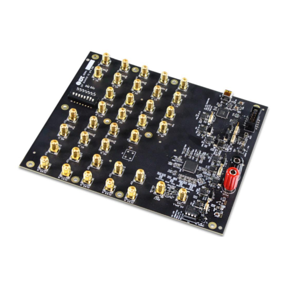
8A3xxxx 72QFN EVK User Manual 1. Usage Guide 1.1 Board Overview The following diagram identifies various components of the board: input and output SMA connectors, power supply jacks, and some jumper settings necessary for the board operations. Figure 1. Overview of 72QFN ClockMatrix Evaluation Board Detailed descriptions of the board are as follows: ... -
Page 5: Board Power Supply
8A3xxxx 72QFN EVK User Manual VDDQx voltage selection jumpers – Each output voltage can be individually supplied with 1.8V, 2.5V, or 3.3V. These jumpers are used to select the voltage for the output voltages. Reset button – A small button is used to reset the board. ... -
Page 6: Gpio Switches, Leds, And Test Points
8A3xxxx 72QFN EVK User Manual The following list shows which head/jumper is used to select what voltage: JP1 – VDDD JP2 – VDDA JP3 – VCC_GPIO_DC JP4 – VDDO_Q8_3_5 JP5 – VDDO_Q2_4_11 JP6 – VDDO_1_10_7 ... -
Page 7: Usb Jack
8A3xxxx 72QFN EVK User Manual Figure 3. GPIO Setting and Status Display Area 1.5 USB Jack The board has a USB mini-connector. The other end of the USB cable is a USB Type A connector going to a PC. 1.6 I C between FTDI, CM Device, and Onboard EEPROM One of the major differences between the 72QFN and 144BGA144 chips is that there is only one serial bus on the 72QFN chip. -
Page 8: Working With Timing Commander™ For Programing/Configuration
The board can operate off an EEPROM that has stored all information including firmware and a default configuration data. A default operation provides a sanity check on the board before running the board through the IDT Timing Commander. Please set the board in the following default conditions (see Figure 4 for jumper and switch positions). -
Page 9: Using Timing Commander To Control The Board
8A3xxxx 72QFN EVK User Manual 2.2 Using Timing Commander to Control the Board Once the default operation is successful, complete the following steps to configure and program the ClockMatrix device per your specific application requirements using Timing Commander GUI tools: 1. -
Page 10: Figure 6. Selecting 8A34001 Using Personality File V4.6
8A3xxxx 72QFN EVK User Manual 3. After selecting “New Settings File”, a device selection window will pop up. In the window, choose the intended device in the list (in this example, 8A34001 is selected). Click the button at the lower right corner of the window (red circle) to browse and select the correct personality file (in this example, personality v4.6 is selected). -
Page 11: Figure 7. Timing Commander Gui With A Settings File Opened
8A3xxxx 72QFN EVK User Manual 4. The GUI window with the 8A34001 block diagram will open for configurations; or if “Open Settings File” is selected in Step 3, you will be prompted to browse and select an existing .tcs file and the personality file. When the configuration file is open, all configured values will be displayed (see Figure 7). -
Page 12: Figure 8. Setting I 2 C For Connecting The Board With Gui
8A3xxxx 72QFN EVK User Manual 5. In order to connect the board with Timing Commander (PC), click the button (red circle) at the up-right corner of the GUI to set up the communication protocols (see Figure 7). After I C and one-byte addressing are selected, click OK to close the window. Figure 8. -
Page 13: Figure 10. Firmware Version Mismatch Warning Message
8A3xxxx 72QFN EVK User Manual 7. If ClockMatrix chip’s firmware, or firmware loaded from EEPROM, has a different version from that in the Personality file, a firmware version mismatch warning message will appear. Click “Close” button to close the message window and a connection is made. Figure 10. -
Page 14: Figure 12. Read Firmware Version Of Clockmatrix Chip
8A3xxxx 72QFN EVK User Manual 9. Within the Firmware Utility window, click the “Get Firmware Version” button to read the firmware version. Figure 12. Read Firmware Version of ClockMatrix Chip 10. In the case where the firmware version mismatches each other, a firmware upgrade is necessary to update the chip’s firmware. To do so, complete the steps in How to Upload Firmware (see Section 3) to update the chip’s firmware. -
Page 15: Output Terminations And Rework To Take 1Pps Input
8A3xxxx 72QFN EVK User Manual 2.3 Output Terminations and Rework to Take 1PPS Input All outputs are terminated with a 100Ω resistor across the output pair. This is the recommended termination regardless of the Voffset and Vswing settings. Since the outputs are DC-coupled, they will support a 1PPS output without any need for rework. Important Equipment Warning: When connecting the outputs to measurement equipment, use a DC-block to ensure... -
Page 16: How To Upload Firmware To The Ram
8A3xxxx 72QFN EVK User Manual 3. How to Upload Firmware to the RAM 1. Connect to the EVK board. 2. Power up the board with no EEPROM present. This ensures the firmware is 4.0.2.7017, as displayed in the figure. 3. The GUI will indicate that the firmware on the chip does not match the GUI firmware. Press “Close”. Open the “Firmware Utility”... - Page 17 8A3xxxx 72QFN EVK User Manual Once the firmware is updated, the following window will indicate a successful update. Click “Close”. Press “Get Firmware Version” to verify that the RAM was updated correctly, then click “Close”. © 2019 Integrated Device Technology, Inc. February 14, 2019...
-
Page 18: Schematics
The information contained herein is provided without representation or warranty of any kind, whether express or implied, including, but not limite d to, the suitability of IDT's products for any particular purpose, an implied warranty of merchantability, or non -infringement of the intellectual property rights of others. This document is presented only as a guide and does not convey any license under intellectual property rights of IDT or any third parties. - Page 19 PROJECT N PROJECT N PROJECT N Indira3 Indira3 Indira3 DESIGN DESIGN DESIGN DRAWN DRAWN DRAWN CHECK CHECK CHECK...
- Page 20 VDDO_Q3 VDDO_Q2 VDDO_Q1 VDDO_Q0 VDDO_Q8 VDD_FOD_0 CLK_Q8_P CLK_Q8_N CLK_Q0_P CLK_Q0_N CLK_Q1_P CLK_Q1_N CLK_Q2_P CLK_Q2_N GPIO0 GPIO4 GPIO5 Maximum voltage on pin 7 = 1.8V U409 VDD_FOD VDDA_0 OSCO OSCO CLK_Q3_P OSCO OSCI VDDO_Q9 OSCI CLK_Q3_N OSCI SILKSCRN: VDD_FOD_0 VDDA_PDCP_XTAL VDDO_Q9 XO_DPLL CLK_Q9_P VDDA_FB...
- Page 21 Board 3V3 OUT_FB C865 C863 IN_CP 1206L350SLTHYR R706 VOUT C838 C841 C842 26.1k 0.01uF 0.1uF VOUT 19-02-14 RvR SENSE 111-0702-001 0.01uF 0.1uF 10uF POST BINDING INSULATED RED GNDPAD 03-09-15 RvR 0.01uF 0.1uF 10uF ADM7171ACPZ-R7 LNJ347W83RA SILKSCRN: 02-09-15 IC REG LDO ADJ 1A 8LFCSP LP38798SD-ADJ/NOPB IC REG LDO ADJ 0.8A 12WSON 19-02-14 RvR...
- Page 22 VDDO_Q8_3_5 SILKSCRN: VDDO_Q2_4_11 3.3V Top OUT_FB 2.5V Bot C810 C811 IN_CP OUT_FB 1.8V Float C814 C815 IN_CP 26.1k 0.01uF 0.1uF 10uF SILKSCRN: 26.1k 0.01uF 0.1uF 10uF VDDO_Q8,Q3,Q5 44.2k R503 VDDA_SEL R501 44.2k 02-09-15 LP38798SD-ADJ/NOPB IC REG LDO ADJ 0.8A 12WSON 02-09-15 LP38798SD-ADJ/NOPB IC REG LDO ADJ 0.8A 12WSON...
- Page 23 1V8_FTDI 3V3_FTDI 5V0_USB R410 VCORE ADBUS0 USB 3V3 R411 VCORE ADBUS1 VOUT VCORE ADBUS2 VOUT ADBUS3 VCCIO ADBUS4 SENSE VCCIO ADBUS5 VCCIO ADBUS6 SILKSCRN: VCCIO ADBUS7 USB PWR VBUS GNDPAD VREGOUT ACBUS0 03-09-15 RvR USBD_P VREGIN ACBUS1 ADM7171ACPZ-R7 LNJ347W83RA R424 USBD_N ACBUS2 IC REG LDO ADJ 1A 8LFCSP...
- Page 24 Note for Silkcreen: Place GPIO[x] lable close to each corresponding LED and Test point. VCC_GPIO_DC VCC_GPIO_DC VCC_GPIO_DC R487 GPIO[0] R488 GPIO[1] R491 GPIO[2] LNJ347W83RA LNJ347W83RA LNJ347W83RA GPIO0 GPIO0 GPIO0 GPIO1 GPIO2 GPIO1 GPIO1 GPIO2 GPIO2 GPIO3 GPIO3 GPIO4 GPIO4 VCC_GPIO_DC VCC_GPIO_DC GPIO5 GPIO5...
- Page 25 SILKSCRN: Place close to OSCI crystal Y3 R469 R470 R468 C759 1.0uF OSCI R471 R472 OSCO 19-03-13 5-1814832-1 C765 10pF C766 10pF I2 Bus JP12~JP15 Default Jump Up 25-11-15 R117 CX3225GB50000P0HPQCC CLK_FTDI_PLL_SCL_OD PLL_I2C_SCL_SCLK CRYSTAL 50.000MHZ 20PPM 18PF SMD R118 JP12 FTDI_PLL_SDA_OD EEPROM_SEL 0552-2-15-01-11-27-10-0...
- Page 26 TP19 SILKSCRN: CLK_EXT_OSC R143 CLK OSC PLACE NEAR OSCILLATOR 20-03-13 RK M6141LF RK 19-03-13 12.8MHZ MERC 9X7 HOT CMOS 3.3V OCXO 5-1814832-1 VDD_CLK0 VDD_CLK0 R912 R913 SILKSCRN: SILKSCRN: CLK0_P CLK4_P R767 49.9 C881 1.0uF R772 49.9 CLK_CLOCK0_P 19-03-13 19-03-13 C883 1.0uF CLK_CLK0_P CLK_CLOCK4_P...
- Page 27 PLACE PARALLEL TERMINATIONS CLOSE TO U58 SILKSCRN: R731 R729 SILKSCRN: R730 Q0_P CLK_Q0_P CLK_Q4_P CLK_Q8_P Q4_P RK 19-03-13 RK 19-03-13 RK 19-03-13 5-1814832-1 5-1814832-1 5-1814832-1 R735 SILKSCRN: R736 SILKSCRN: R737 CLK_Q0_N CLK_Q4_N CLK_Q8_N Q0_N Q4_N RK 19-03-13 RK 19-03-13 RK 19-03-13 5-1814832-1 5-1814832-1 5-1814832-1...
- Page 28 VDDA VDDA_0 VDD_CLK0 VDD_CLK0_0 R875 R876 VDDA_1 R877 VDD_FOD R879 VDD_FOD_0 R882 VDD_FOD_2 VDDO_Q8_3_5 VDDO_Q8 VDDO_Q1_10_7 VDDO_Q1 R885 R886 R887 VDD_FOD_5 VDDO_Q3 VDDO_Q10 L100 R888 L103 R889 L104 VDDO_Q5 VDDO_Q7 R891 L105 R892 L106 VDDO_Q0_9_6 VDDO_Q0 VDDO_Q2_4_11 VDDO_Q2 R894 R895 VDDO_Q9 VDDO_Q4 R896...
- Page 29 X-ON Electronics Largest Supplier of Electrical and Electronic Components Click to view similar products for category: Clock & Timer Development Tools Click to view products by manufacturer: Other Similar products are found below : EV-ADF4106SD1Z EV-ADF4156SD1Z 118777-HMC720LP3E AD9512/PCBZ AD9516-0PCBZ AD9516-3PCBZ AD9517-0A/PCBZ AD9517-1A/PCBZ AD9517-2A/PCBZ AD9522-4/PCBZ AD9552PCBZ 125614-HMC850LC3 EKIT01-HMC767LP6CE NBA3N206SDGEVB EV-ADF4355-3SD1Z AD9516-1/PCBZ AD9516-4PCBZ AD9520-5PCBZ AD9530/PCBZ AD9547/PCBZ AD9553/PCBZ AD9557PCBZ AD9559/PCBZ LMH2180SDEVAL 105706-HMC429LP4 108648-HMC733LC4B 110227-HMC734LP5...
Need help?
Do you have a question about the 8A 72QFN Series and is the answer not in the manual?
Questions and answers