Ecler VEO-XTI2L User Manual
Video over ip distribution low latency 4k over ip video extenders with kvm and video wall functionality
Hide thumbs
Also See for VEO-XTI2L:
- User manual (44 pages) ,
- Tcp/ip control manual (17 pages) ,
- Quick start manual (12 pages)

Related Manuals for Ecler VEO-XTI2L


Summary of Contents for Ecler VEO-XTI2L
- Page 1 VEO-XTI2L / VEO-XRI2L VIDEO OVER IP DISTRIBUTION Low latency 4K over IP video extenders with KVM and video wall functionality USER MANUAL V20220105...
-
Page 2: Table Of Contents
CONTENTS IMPORTANT REMARK ......................5 IMPORTANT SAFETY INSTRUCTIONS ................5 NOTA IMPORTANTE ......................7 INTRODUCTION ........................7 PACKAGE CONTENTS ......................8 PANEL DESCRIPTIONS ......................9 6.1. Transmitter ........................... 9 6.1.1. Front panel ..........................9 6.1.2. Rear panel ........................... 10 6.2. Receiver ............................11 6.2.1. - Page 3 CONFIGURATION USING ECLERNET MANAGER ............21 9.1. How to find devices in EclerNet Manager ................ 21 9.2. How to add VEO-XTI2l and VEO-XRI2L to an EclerNet Manager project ..... 23 9.3. Which functions are available when operating the devices via EclerNet Manager? ................................
- Page 4 11.4. Configuring operating functions ..................49 11.4.1. Setting the video output mode for the receiver ............ 50 11.4.2. Setting the scalar output mode for the transmitter ..........52 11.4.3. USB over IP data extension ..................52 FIBRE OPTIC CONNECTION ....................54 FACTORY RESET ........................
-
Page 5: Important Remark
IMPORTANT REMARK The lightning flash with arrowhead symbol, within an equilateral triangle, is intended to alert the user to the presence of uninsulated “dangerous voltage” within the product’s enclosure that may be of sufficient magnitude to constitute a risk of electric shock to persons. The exclamation point within an equilateral triangle is intended to alert the user to the presence of important operating and maintenance (servicing) instructions in the literature accompanying the appliance. - Page 6 8. Do not install near any heat sources such as radiators, heat registers, stoves, or other apparatus (including amplifiers) that produce heat. 9. Do not defeat the safety purpose of the polarized or grounding type plug. A polarized plug has two blades with one wider than the other. A grounding type plug has two blades and a third grounding prong.
-
Page 7: Nota Importante
NOTA IMPORTANTE Thank you for choosing our VEO-XTI2L & VEO-XRI2L Low Latency 4K Video Over IP Extenders! VERY IMPORTANT It is to carefully read this manual and to fully understand its contents before any connection in order to maximize your use and get the best performance from this equipment. -
Page 8: Package Contents
• Support for PoE (Power over Ethernet) or 5V-18V external power. PACKAGE CONTENTS VEO-XTI2L Package • 1 x 4K over IP transmitter • 1 x IR remote control • 1 x IR TX cable • 2 x IR RX cable •... -
Page 9: Panel Descriptions
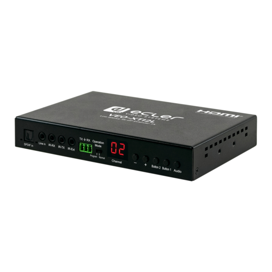
PANEL DESCRIPTIONS 6.1. Transmitter 6.1.1. Front panel 1. Not enabled 2. Not enabled 3. Analogue audio status indicator 4. Line input connector for analogue audio 5. IR-RX connector for IR sensor 6. IR-TX connector for IR emitter 7. IR sensor for remote control 8. -
Page 10: Rear Panel
6.1.2. Rear panel 1. Reset button (push for 1 second to reset the device) 2. Fibre optic connection indicator 3. Fibre optic SFP receptacle 4. Cat. 5e/6 connector 5. HDMI input port 6. USB input (Type B) 7. DC 5V input connector 8. -
Page 11: Receiver
6.2. Receiver 6.2.1. Front panel 1. S/PDIF status indicator 2. Audio Output S/PDIF Connector 3. Analogue audio status indicator 4. Analogue audio line out connector 5. IR-RX connector for IR sensor 6. IR-TX connector for IR emitter 7. IR sensor for remote control 8. -
Page 12: Rear Panel
6.2.2. Rear panel 1. Reset button (push for 1 second to reset the device) 2. Fibre optic connection indicator 3. Fibre optic SFP receptacle 4. Cat. 5e/6 connector 5. HDMI output port 6. USB input (Type A) 7. DC 5V input connector 8. -
Page 13: Group Id Selection Using Remote Control
6.4. Group ID selection using remote control The Group ID, or group identifier can be selected using the IR remote controller included. You must ensure that the IR-Ext sensor is connected (see ‘Package contents’ chapter). The remote control can be used to change the group ID, as explained below. •... -
Page 14: Description Of The Function Buttons
6.6. Description of the audio control button Transmitter The "Audio" button on the VEO-XTI2L transmitter allows the "Line in" input to be selected. The external audio will be embedded in the video stream of the HDMI input, overwriting any original audio that may exist Receiver The "Audio"... -
Page 15: Installation And Configuration
7.2. How to find out the IP address of devices VEO-XTI2L and VEO-XRI2L devices have the "Auto IP" function set by default. This provides automatic IP address assignment on devices that are connected to the same network. - Page 16 Receiver • Connect the HDMI output of the receiver to a display. The receiver will display the IP address information in the lower right-hand corner of the monitor. The 'Local IP' is the address for the receiver Transmitter • Connect the transmitter, with no source connected to the HDMI input on the receiver.
-
Page 17: Requirements And Recommendations For Using A Veo Ip Video Network
7.3. Requirements and recommendations for using a VEO IP video network It is necessary to use gigabit switches with support for Jumbo Frame (or, if this is not available, the ability to extend the size of the IP packet) and IGMP. This will create the most appropriate scenario both for standalone IP video networks, and for cases where IP video systems share the network with other data streams. -
Page 18: System Topology And Configurations
8.1. Point-to-point connection When the VEO-XTI2L and VEO-XRI2L are connected as a simple extension within a point-to-point topology, no configuration is required. The devices have a default setting of "Auto IP" (169.254.x.x), and each transmitter will send a unicast video stream to the corresponding receiver when the same Group ID is selected. -
Page 19: Multipoint-To-Multipoint Connections And Operations
8.3. Multipoint-to-multipoint connections and operations When the VEO-XTI2L and VEO-XRI2L are to be used as an IP matrix system within a multipoint-to-multipoint connection, both the transmitters and the receivers must be configured as multicast devices. Each receiver can decode the stream related to the group ID of the desired transmitter. -
Page 20: Video Wall Mode
8.5. Video wall mode When the VEO-XTI2L and VEO-XRI2L are to be used in video wall mode, both the transmitters and the receivers must be configured as multicast devices. Each receiver must be set to the same Group ID as the transmitter, following the instructions provided in the ‘Configuring video wall mode using the control... -
Page 21: Configuration Using Eclernet Manager
Start up the EclerNet Manager software and select the corresponding network card. Then, open the "Online and Unused Device List" tab. The software will automatically discover all the VEO-XTI2L and VEO-XRI2L devices present on the network and list them in the window in question. - Page 22 If you need to modify any of the network parameters of the discovered pieces of equipment, simply right-click on the selected element to display the action menu, and choose the "Network Configuration" option, where you can modify the information related to the network identifier.
-
Page 23: How To Add Veo-Xti2L And Veo-Xri2L To An Eclernet Manager Project
IP address to the desired range. 9.2. How to add VEO-XTI2l and VEO-XRI2L to an EclerNet Manager project Once all the devices have been discovered, they can be incorporated into an EclerNet Manager project by simply dragging each individual element into any of the work areas of the software, shown with a green box. - Page 24 As soon as this process is completed, the added devices will appear in the "Devices" window and disappear from the "Online and Unused Device List" box. If the green indicator appears, it means that these elements are ready to be configured and/or used.
- Page 25 Otherwise, if the indicator is red, you need to investigate the reason for this. The most likely reason is that this equipment is not within the same network range as the control computer.
-
Page 26: Which Functions Are Available When Operating The Devices Via Eclernet Manager
9.3.1. VEO-XTI2L Transmitter Associated Functions You will be able to control the following parameters for the VEO-XTI2L transmitter: • CONFIG: this section allows you to select "Unicast" or "Multicast" transmission mode •... -
Page 27: Veo-Xri2L Transmitter Associated Functions
9.3.2. VEO-XRI2L Transmitter Associated Functions You will be able to control the following parameters for the VEO-XRI2L transmitter: • CONFIG: this section allows you to select "Unicast" or "Multicast" transmission modes, on the one hand, and the "Videowall" operating mode. In addition, you can set and adjust the dimensions and layout of an image once it is activated... -
Page 28: How To Add Control Functions To A Ucp (User Control Panel)
• NETWORKING: This section opens the dialogue box that allows you to modify the device's network information • SETTINGS: Channel Selection: This parameter allows you to select the transmission channel that the receiver will work on o Video Mute Out: This function allows you to activate/deactivate the output video signal on the receiver 9.3.3. -
Page 29: Configuration Using Veo Xti2L - Xri2L Control Centre
EclerNet Manager. In this case, the only available way to manage the equipment will be by means of the VEO-XTI2L - XRI2L Control Centre utility software for PC. Once the software is installed, make sure that the PC and the VEO devices are within the same network domain. -
Page 30: Configuring The Casting Mode Using The Control Centre
In order to change parameters, such as the IP address, host ID, casting mode or Ip mode, just select the device you want to configure and enter the required data. This page also allows you to perform a device reset or a factory reset from the remote control of the selected device. -
Page 31: Configuring Video Wall Mode Using The Control Centre
10.3. Configuring video wall mode using the Control Centre To put together a video wall, the transmitters and receivers must be configured with the same IP multicast (group ID). The group ID of each device can be selected using software. Each group ID corresponds to a multicast IP address, as shown below. - Page 32 By activating the "Show OSD" function, an OSD number will be assigned and displayed on each screen. This is a useful feature for identifying each receiver and monitor. You need to drag and drop the OSD number received in the corresponding position on the video wall, as shown below: Press "Apply"...
-
Page 33: Configuration Using The Web Interface
11.1. Configuring the system settings 11.1.1. Firmware information and updating The "System" tab includes "Version Information", which displays the firmware version and, in addition, product-related information. In the event that you need a firmware update, please contact Ecler technical support. -
Page 34: Utilities
11.1.2. Utilities The "Utilities" tab allows you to restore the device to factory default settings, or to reset the unit from the remote control. It is also possible to test the API commands through the API command line console. -
Page 35: Statistics
11.1.3. Statistics This tab displays more information, such as equipment status, network settings, and information regarding video resolution and timing. -
Page 36: Configuring Video Wall Mode Using The Web Interface
11.2. Configuring video wall mode using the web interface 11.2.1. Basic configuration procedure The video wall configuration includes "Basic" and "Advanced" configurations. Under "Basic Setup", the main settings for putting together the video wall are provided. Through this page, you can set the size of the video wall structure (transmitter and receiver must be set to the same size), the position of the screen, the bezel and gap compensation and the rotation or stretching of the screen. -
Page 37: Bevel And Gap Compensation
11.2.2. Bevel and gap compensation: Screen dimensions (inside and outside width and height) • OW: outside width • OH: outside height • VW: visible width • VH: visible height 1. The visible width must be less than the outside width, and the visible height must be less than the outside height 2. -
Page 38: Size Of The Structure And Position Layout
11.2.3. Size of the structure and position layout You need to select the number of vertical and/or horizontal monitors, the position of the rows and the position of the columns. The horizontal and vertical monitor number must be included, and it should be between 1 and 8. -
Page 39: Preferences
11.2.4. Preferences Select the video stretching and rotation option. The image can fit within the screen, or be stretched and rotated through 180 or 270 degrees. -
Page 40: Apply To
11.2.5. Apply to • All: Configures all transmitters and receivers within the same IP group • This (Local): Configures the current device (IP address indicated in the web browser) • Hosts or Clients: selects the transmitter or receiver that is to be configured from the web page in use •... -
Page 41: Advanced Configuration
11.2.6. Advanced configuration This session allows for some additional fine tuning. Before entering "Advanced Setup", complete the "Basic Setup", defining and confirming the layout and size of the video display. - Page 42 If a 3x5 video structure is required, for example, once the basic configuration has been applied, the first advanced configuration session will look like this. You can make changes to a group of screens by simply selecting the target devices. If there are errors in the settings, the "Reset"...
- Page 43 The video offsetting and scaling can be adjusted through the following parameters: Horizontal Shift: Adjusts the horizontal shift of the video, Left or Right Vertical Shift: Adjusts the vertical shift of the video, Up or Down...
- Page 44 Horizontal Scale Up: Adjusts the horizontal scaling of the video up Vertical Shift Scale Up: Adjusts the vertical scaling of the video up...
-
Page 45: Configuring Network Settings
11.3. Configuring network settings The "Network" page allows you to adjust the network settings and casting mode for each device. 11.3.1. Auto IP Auto IP (default) enables automatic IP address assignment when more devices are connected to the same network. The factory-assigned IP subnet is 169.254.x.y. The last two numbers are randomly generated within a pre-set range. -
Page 46: Dhcp (Dynamic Host Configuration Protocol)
11.3.2. DHCP (Dynamic Host Configuration Protocol) If you are using a network switch or a LAN that has a DHCP server enabled on it, it will automatically assign a unique IP address to each device. Refer to the instructions in the ‘How to find out the IP address of devices’... -
Page 47: Configuring A Static Ip Address
11.3.3. Configuring a static IP address When static IP addresses are required, you need to change the IP address of each device manually. Once the default "Auto IP" address has been found, you can access the configuration web page by simply typing the device address into a web browser. The control PC must be within the same network domain as the VEO products. -
Page 48: Casting Mode
11.3.4. Casting Mode Select the casting mode according to the application for which the extender is being used: • Multicast: required for casting applications, matrix structures or point-to-multipoint and multipoint-to-multipoint video walls • Unicast: required for point-to-point extension applications The "Auto select USB operation mode per casting mode" allows you to change the behaviour of the USB pass-through according to the selected casting mode. -
Page 49: Configuring Operating Functions
11.4. Configuring operating functions The "Functions" page allows you to configure the video output, the USB extension mode and the "Serial over IP" function, both for the transmitter and the receiver. The receiver page will look like this:... -
Page 50: Setting The Video Output Mode For The Receiver
11.4.1. Setting the video output mode for the receiver • Enable Video over IP: Select this box to activate Video over IP extension • Enable Video Wall: Select to activate the function for putting together a video wall • Enable EDID Copy: This function allows you to copy the EDID output and send the information to the Transmitter. - Page 51 • Not active: if this box is not selected, the time frame entered in the "Timeout for Detecting Video Lost" parameter will define the interval between the moment when video is no longer detected and the moment when the VEO-XRI2L information screen appears •...
-
Page 52: Setting The Scalar Output Mode For The Transmitter
If the "Never Timeout" parameter is selected as the time frame, then the last video frame prior to the loss of video signal will be remain indefinitely, until another video stream is detected or the transmitter is restarted. 11.4.2. Setting the scalar output mode for the transmitter On the Transmitter Function page, you can select the maximum transmission speed for the generated transmission. - Page 53 Type 2 guest mode: allows the VEO-XTI2L and VEOXRI2L to act as translators of TCP/IP and RS-232 communication. To do so, you will need to create a TCP/IP connection using the device's IP address and port 6752.
-
Page 54: Fibre Optic Connection
FACTORY RESET For these VEO devices, you can perform a factory reset using the VEO-XTI2L-XRI2L Control Centre (see the ‘Configuration using VEO-XTI2L-XRI2L Control Centre’... -
Page 55: Technical Specifications
TECHNICAL SPECIFICATIONS Resolution 3840X2160@30HZ 3840X2160@60Hz (4:2:0) supported and converted to 3840X2160@30Hz, 1080P/1080i/720P/576P/576i/480P/480i Video connectors HDMI 1.4 with thread lock HDCP 2.2 Compliant Network requirements Accordance with IGMP and Jumbo Frames Network transmission bit rate Up to 300Mbps Video latency 1 to 3 frames depending on network conditions Network connectors RJ45 with LED indication and SFP receptacle Default IP... - Page 56 Humidity 5 - 90% RH (non-condensing) Energy consumption 3 W MAX (TX y RX) Input supply AC100~240V 50/60Hz Output: DC 5V/1A Dimensions A x A x P 26mm x 170mm x 109mm (1.02” x 6.69” x 4.29”) (TX y RX) Weight 470g (1,036 lbs.)
- Page 57 For technical inquiries, please contact your supplier, distributor or fill in the contact form on our website under Support/Technical Inquiries. Motors, 166-168 08038 Barcelona - Spain - (+34) 932238403 | information@ecler.com www.ecler.com...
Need help?
Do you have a question about the VEO-XTI2L and is the answer not in the manual?
Questions and answers