Table of Contents
Advertisement
Quick Links
88 5544 42
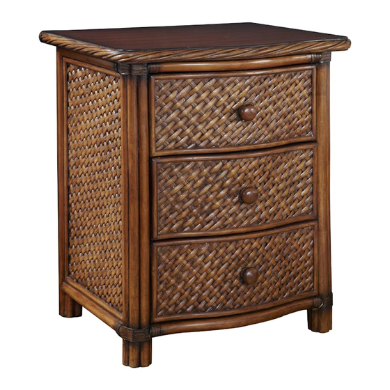
Marco Island
Night Stand
IMPORTANT NOTE
Carefully remove all the parts from the carton and put
them individually on a soft cloth to prevent scratches
or other damages occuring to the wood parts.
We have taken great care in the design of this
product and request that you carefully and strictly
follow our assembly instructions to ensure a
completed product as it was designed.
A.
Top
1 pc.
B.
Side Panel
1 pc.
Hardware List
"
1 1/2 Round Head Screw
3 pcs.(+1 extra)
Tools required for assembly : Phillips screwdriver
Home Styles Consumer Assistance: www.homestyles-furniture.com,
servicedesk@homestyles-furniture.com, 888-680-7460, 877-831-0319
E.
Front rail
1 pc.
C.
Side Panel
1 pc.
"
1 1/4 Flat Head Screw
24 pcs.(+1 extra)
F.
Back rail
1 pc.
(Knock-Down Construction, please refer
to the last page of instructions for steps
to complete drawer assembly)
Cam Lock Screw
Cam Lock
8 pcs.(+1 extra)
8 pcs.(+4 extra)
G.
Back Panel
1 pc.
D.
Drawer
3 pcs.
Pull Handle
3 pcs.
Advertisement
Table of Contents

Related Manuals for Homestyles Marco Island 88 5544 42


Summary of Contents for Homestyles Marco Island 88 5544 42
- Page 1 1 1/4 Flat Head Screw Cam Lock Screw Cam Lock Pull Handle 3 pcs.(+1 extra) 24 pcs.(+1 extra) 8 pcs.(+1 extra) 8 pcs.(+4 extra) 3 pcs. Tools required for assembly : Phillips screwdriver Home Styles Consumer Assistance: www.homestyles-furniture.com, servicedesk@homestyles-furniture.com, 888-680-7460, 877-831-0319...
- Page 2 Assembly Instructions 2/5 IMPORTANT * Do not tighten up all the screws until each part is properly assembled. * Use a soft cloth between these parts and the floor. STEP 1 Insert Cam Lock Screws into the pre-drilled holes of Side Panels (B) and (C).
- Page 3 Assembly Instructions 3/5 STEP 3 Attach Top (A) to unit with Cam Locks. (See Figure 2) Figure 2 STEP 4 Slide Back Panel (G) into position.
- Page 4 Assembly Instructions 4/5 STEP 5 Attach Side Panel (C) to unit with Cam Locks. (See Figure 3) Figure 3 STEP 6 Slide Drawers (D) into position.
- Page 5 Assembly Instructions 5/5 Drawer (D) STEP 1 Attach Side Part (D3) to Front Part (D1) and Back Part (D2) using 1 1/4” Flat Head Screws. STEP 2 Insert Base Part (D5) into the groove. Attach Side Part (D4) to unit using 1 1/4”...
Need help?
Do you have a question about the Marco Island 88 5544 42 and is the answer not in the manual?
Questions and answers