Table of Contents
Advertisement
Quick Links
Advertisement
Chapters
Table of Contents
Troubleshooting

Subscribe to Our Youtube Channel
Related Manuals for Mitsubishi Heavy Industries SL Series


Summary of Contents for Mitsubishi Heavy Industries SL Series
- Page 1 SERVICE MANUAL July 2016 99619-12150 Pub. No. Printed in Japan...
- Page 3 INTRODUCTION This service manual describes the specifications, maintenance and service procedures for Mitsubishi diesel engines. To maintain the performance of the engine for many years and to ensure safe operation, it is important to use the engine correctly and conduct regular inspection and maintenance, and also to take necessary measures which involves the disassembly, inspection, repair and reassembly of the engine and engine parts.
- Page 5 INTRODUCTION How to use this manual This service manual consists of several Groups, which are arranged so as to allow you to make reference quickly to specifications, maintenance standards, adjustment procedures and service procedures including methods for disassembly, inspection, repair and reassembly of the Mitsubishi Diesel Engine (standard model for land use). A short summary describing the content of each Group is given in the General Contents page, and there is also a detailed table of contents at the beginning of each Group.
- Page 6 INTRODUCTION Terms used in this manual Nominal means the rated (design) size or magnitude of a part to be measured. Standard means the quantitative requirement for dimension of a part, clearance between parts and performance. This is given in a form of tolerance.
- Page 7 INTRODUCTION Safety Cautions Fire and explosion Keep flames away Care about fuel, oil and exhaust gas leakage Store fuel and engine oil in a well If any fuel, oil or exhaust gas leakage is found, immedi- ventilated designated area. ately take corrective measures to stop it. Make sure that the caps of fuel and Such leakages, if left uncorrected, can cause fuel or engine oil containers are tightly...
- Page 8 INTRODUCTION Stay clear of all rotating and moving parts Install protective covers on rotating parts Lockout and Tagout Make sure the protective covers for Be sure to lockout and tagout before starting inspection engine rotating parts are properly and maintenance. installed as intended.
- Page 9 INTRODUCTION Be careful of burns Be careful of exhaust fume poi- soning Do not touch the engine during or immedi- ately after operation Operate engine in well-ventilated area Do not touch the engine during or If the engine is installed in an en- immediately after operation...
- Page 10 INTRODUCTION Be careful of falling down Be careful of handling fuel, engine oil and LLC Lift engine correctly To lift the engine, always use a cor- Use only specified fuel, engine oil and long- rect wire rope capable of withstand- life coolant (LLC) ing the engine weight.
- Page 11 INTRODUCTION Service battery When abnormality occurs Handle the battery correctly Stop overheated engine after cooling run • Never use flames or allow sparks Even if the engine comes to overheat, do not stop the to generate near the battery. The engine immediately.
- Page 12 INTRODUCTION Other cautions Modification of engine prohibited Warming-up operation Unauthorized modification of the engine will void the After starting the engine, run the engine at low idling manufacturer’s warranty. speeds for 5 to 10 minutes for warming-up. Start the Modification of the engine may not only cause engine work after this operation is completed.
- Page 13 INTRODUCTION Maintenance of air cleaner or pre-cleaner Avoidance of prolonged time of starter oper- The major cause of abnormal wear on engine parts is ation dust entering with intake air. Worn parts produce many Do not operate the starter for more than 10 seconds at problems such as an increase of oil consumption, de- a time even if the engine does not start.
- Page 14 INTRODUCTION About warning labels Maintenance of warning labels Make sure all warning/caution labels are legible. Clean or replace the warning/caution labels when the description and/or illustration are not clear to read. For cleaning the warning/caution labels, use a cloth, water and soap. Do not use cleaning solvents, gasoline or other chemicals to prevent the letters from getting blurred or the adhesion from being weakened.
-
Page 15: Table Of Contents
GENERAL CONTENTS Group Name Contents Group No. External view System flow diagrams General Engine serial number location Specifications Tips on disassembling and reassembling Maintenance service data Service data Tightening torque table Basic tools Service tools Special tools Determining overhaul timing Determination of overhaul Testing compression pressure Disassembling and inspecting cylinder head and valve mechanism... -
Page 17: General
GENERAL 1. External view........1-2 1.1 External view of S3L and S3L2....1-2 1.2 External view of S4L and S4L2....1-3 2. System flow diagrams .....1-4 2.1 Fuel system - flow diagram ...... 1-4 2.2 Lubrication system - flow diagram ... 1-4 2.3 Cooling system - flow diagram.... -
Page 18: External View
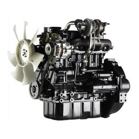
GENERAL 1. External view 1.1 External view of S3L and S3L2 Oil inlet Thermostat Hanger Exhaust manifold Alternator Starter Front Rear V belt Flywheel Oil pan Left side Engine left view Fuel injection nozzle Inlet cover Water pump Stop solenoid Fuel injection pump Coolant drain plug Rear... -
Page 19: External View Of S4L And S4L2
GENERAL 1.2 External view of S4L and S4L2 Oil inlet Thermostat Hanger Exhaust manifold Alternator Starter Front Rear Flywheel V belt Oil pan Left side Engine left view Fuel injection nozzle Inlet cover Water pump Stop solenoid Fuel injection pump Coolant drain plug Front Rear... -
Page 20: System Flow Diagrams
GENERAL 2. System flow diagrams 2.1 Fuel system - flow diagram Fuel leak-off pipe Fuel injection pipe To fuel tank Fuel injection nozzle Fuel pump Fuel injection pump Fuel filter From fuel tank Fuel system - flow diagram 2.2 Lubrication system - flow diagram Oil pressure switch Oil main gallery Oil filter... -
Page 21: Cooling System - Flow Diagram
GENERAL 2.3 Cooling system - flow diagram Water bypass hose Water pump Thermostat Radiator Cooling fan Cooling system - flow diagram 2.4 Inlet and exhaust system - flow diagram Exhaust Inlet Air breather pipe (blow-by gas reduction) Blow-by gas Inlet From air cleaner Exhaust To muffler... -
Page 22: Engine Serial Number Location
GENERAL 3. Engine serial number location The engine serial number is stamped on the upper side of Engine serial number the fuel injection pump installation part located in the right side of cylinder block. Stamp location of engine serial number... -
Page 23: Specifications
GENERAL 4. Specifications This specifications may differ from your engine specifications. Table 1-1 Specifications (1 / 3) Engine model S3L2 S4L2 S4L2-T Water-cooled, 4-stroke cycle, Type Water-cooled, 4-stroke cycle diesel turbocharged diesel No. of cylinders Combustion type Swirl chamber type Valve mechanism Overhead valve type 78 ×... - Page 24 GENERAL Table 1-1 Specifications (2 / 3) Engine model S3L2 S4L2 S4L2-T Type Bosch M type Manufacturer DENSO corporation Fuel Plunger diameter ø 5.5 mm [0.217 in.] or ø 6.0 mm [0.236 in.] injection pump MS retard 4°, 8° or no setting (crank angle) Cam lift 15 mm [0.59 in.]...
- Page 25 GENERAL Table 1-1 Specifications (3 / 3) Engine model S3L2 S4L2 S4L2-T Voltage - polarity 12V - negative (-) ground, 24V - negative (-) ground Type M001T68281, M008T70471A, M008T81071A Manufacturer Mitsubishi Electric Corporation Pinion engage- Pinion shift (reduction type) ment type Starter Output 12 V - 1.7 kW, 12 V - 2.0 kW, 24 V - 3.2 kW...
-
Page 26: Tips On Disassembling And Reassembling
GENERAL 5. Tips on disassembling and reassem- bling This service manual specifies the recommended procedures to be followed when servicing Mitsubishi engines. The manual also specifies the special tools that are required for the work, and the basic safety precautions to follow when working. -
Page 27: Service Data
SERVICE DATA 1. Maintenance service data ....2-2 1.1 General ............ 2-2 1.2 Basic engine ..........2-2 1.3 Fuel system..........2-5 1.4 Lubrication system ........2-5 1.5 Cooling system ........2-5 1.6 Inlet and Exhaust system......2-5 1.7 Electrical system ........2-6 2. -
Page 28: Maintenance Service Data
SERVICE DATA 1. Maintenance service data 1.1 General Table 2-1 Maintenance service data table - General Unit: mm [in.] Inspection point Nominal Standard Limit Remark Maximum rotation speed (Varies depending on specification of desti- (rated rotation speed used as reference) nation) Minimum rotation speed 2.9 MPa... - Page 29 SERVICE DATA Table 2-2 Maintenance service data table - Basic engine (2 / 3) Unit: mm [in.] Inspection point Nominal Standard Limit Remark Valve seat angle 45° Seat width 0.25 to 0.75 1.50 Valve sinkage [0.00] [0.0098 to 0.0295] [0.0591] 1.30 to 1.80 2.50 Valve seat...
- Page 30 SERVICE DATA Table 2-2 Maintenance service data table - Basic engine (3 / 3) Unit: mm [in.] Inspection point Nominal Standard Limit Remark No.1 compres- 0.09 to 0.11 0.30 sion ring [0.0035 to 0.0043] [0.0118] Use the piston with replac- ing the piston rings until Clearance between piston No.2 compres-...
-
Page 31: Fuel System
SERVICE DATA 1.3 Fuel system Table 2-3 Maintenance service data table - Fuel system Unit: mm [in.] Inspection point Nominal Standard Limit Remark 13.73 MPa 14.22 to 15.00 MPa Valve opening pres- Adjust with washers Fuel injection nozzle {140 kgf/cm²} {145 to 153 kgf/cm²} sure Standard is new parts value. -
Page 32: Electrical System
SERVICE DATA 1.7 Electrical system Table 2-7 Maintenance service data table - Electrical system Unit: mm [in.] Inspection point Nominal Standard Limit Remark Adjust Pinion gap 0.5 to 2.0 [0.020 to 0.079] with pack- M001T68281 M008T70471A M008T81071A Voltage 11 V 11 V 23 V No-load... -
Page 33: Tightening Torque Table
SERVICE DATA 2. Tightening torque table 2.1 Major bolt tightening torque 2.1.1 Basic engines Table 2-8 Tightening torque list - Basic engines Threads Torque Description Dia × Pitch Remark N·m kgf·m lbf·ft (mm) Cylinder head bolt M10 × 1.75 83.4 to 93.2 8.5 to 9.5 61.5 to 68.7 Rocker cover bolt... -
Page 34: Lubrication System
SERVICE DATA 2.1.3 Lubrication system Table 2-10 Tightening torque list - Lubrication system Threads Torque Description Dia × Pitch Remark N·m kgf·m lbf·ft (mm) Oil relief valve M22 × 1.5 44.1 to 53.9 4.5 to 5.5 32.5 to 39.8 Oil pan drain plug M14 ×... -
Page 35: Standard Bolt And Nut Tightening Torque
SERVICE DATA 2.2 Standard bolt and nut tightening torque Table 2-14 Standard bolt and nut tightening torque Threads Width Strength classification Description Dia × Pitch across flats 10.9 (mm) (mm) [in.] N·m kgf·m lbf·ft N·m kgf·m lbf·ft M8 × 1.25 12 [0.47] M10 ×... -
Page 36: Standard Eyebolt Tightening Torque
SERVICE DATA 2.3 Standard eyebolt tightening torque Table 2-15 Standard eyebolt tightening torque Strength classification Threads Width Dia × Pitch across flats (mm) (mm) [in.] N·m kgf·m lbf·ft M8 × 1.25 12 [0.47] 8 ± 1 0.8 ± 0.1 6 ± 0.7 M10 ×... -
Page 37: Service Tools
SERVICE TOOLS 1. Basic tools ........3-2 2. Special tools ........3-3... - Page 38 SERVICE TOOLS 1. Basic tools Table 3-1 Basic tools list Tool name Part No. Tool set MM413900 Includes 1 to 5 Width across flats Spanner MK96008010 (8 mm × 10 mm) [0.32 × 0.39 in.] Width across flats Spanner MK96012014 (12 mm ×...
- Page 39 SERVICE TOOLS 2. Special tools Tool name Part No. Illustration Piston pin Piston pin setting tool 31A91-00100 removal/installation Punching/press-fitting of Camshaft bushing installer ST332340 front camshaft bushing Compression gauge adapter ST332270 Compression measuring Oil pressure switch socket Oil pressure switch MD998054 wrench (26) removal/installation...
-
Page 41: Determination Of Overhaul
DETERMINATION OF OVERHAUL 1. Determining overhaul timing ...4-2 2. Testing compression pressure ..4-3... -
Page 42: Determining Overhaul Timing
DETERMINATION OF OVERHAUL 1. Determining overhaul timing In most cases, the engine should be overhauled when the compression pressure of the engine becomes low. An increase in engine oil consumption and blow-by gas are also considered to evaluate the engine condition. Besides, such symptoms as a decrease in output, increase in fuel consumption, decrease in oil pressure, difficulty of engine starting and increase in noise are also considered for judging the overhaul timing, although those symptoms are often affected by other causes, and are not always effective to judge the overhaul timing. - Page 43 DETERMINATION OF OVERHAUL 2. Testing compression pressure (a) Be sure to measure the compression pressure for Compression all the cylinders. It is not a good practice to mea- gauge sure the compression pressure for only one cylin- der, and presume the compression for the Compression remaining cylinder.
- Page 45 DISASSEMBLY OF BASIC ENGINE 1. Disassembling and inspecting cylinder head and valve mechanism5-2 1.1 Removing rocker shaft assembly..... 5-3 1.2 Disassembling rocker shaft assembly..5-3 1.3 Removing cylinder head bolt....5-3 1.4 Removing cylinder head assembly ..5-4 1.5 Removing valves and valve spring ..5-4 1.6 Removing valve stem seal .......
-
Page 46: Disassembly Of Basic Engine
DISASSEMBLY OF BASIC ENGINE 1. Disassembling and inspecting cylinder head and valve mechanism Spring fatigue Clogged oil hole End face wear, damage Damaged threads Wear Bend Worn rocker shaft, Clogged oil hole Spring fatigue, damage Valve guide wear, damage Bottom face distortion Cracks, Damage, Coolant leakage, Oil leakage, Scale formation, Valve seat contact,... -
Page 47: Removing Rocker Shaft Assembly
DISASSEMBLY OF BASIC ENGINE 1.1 Removing rocker shaft assembly (1) Loosen the rocker arm adjusting screw by about one turn. (2) Loosen the rocker stay bolts and remove the rocker shaft assembly. Note: When removing the rocker shaft assembly, remove it together with the rocker stay bolts, and keep them together for reassembling. -
Page 48: Removing Cylinder Head Assembly
DISASSEMBLY OF BASIC ENGINE 1.4 Removing cylinder head assembly When removing the cylinder head gasket, be careful not to damage the cylinder head or crankcase surface by tools such as a screwdriver. (1) Remove the cylinder head bolt. (2) Remove the cylinder head assembly by lifting it up. Note: If the cylinder head assembly cannot be removed due to crimping of the cylinder head gasket, tap the thick area on the side of the cylinder head using a plastic... -
Page 49: Disassembling And Inspecting Flywheel
DISASSEMBLY OF BASIC ENGINE 2. Disassembling and inspecting flywheel Replace Oil seal wear, damage, deterioration Cracks, Damage Frictional surface streak, stepped wear, cracks, Ring gear damage, abnormal wear Disassembling and inspecting flywheel Disassembling sequence 1 Flywheel 3 Rear plate 2 Flywheel housing 4 Oil seal case, oil seal... -
Page 50: Removing Flywheel
DISASSEMBLY OF BASIC ENGINE 2.1 Removing flywheel (a) Be careful not to cut yourself with the ring gear when pulling out the flywheel. Be careful not to drop or hit the flywheel when removing. (b) The personnel who holds the pulley must pay due attention to safety. -
Page 51: Removing Oil Seal Case
DISASSEMBLY OF BASIC ENGINE 2.4 Removing oil seal case Be very careful not to damage the oil seal. (1) Remove bolts from the oil seal case. (2) Pry out the oil seal case from the cylinder block using a screwdriver. Removing oil seal case... -
Page 52: Disassembling And Inspecting Gear Case, Timing Gear And Camshaft
DISASSEMBLY OF BASIC ENGINE 3. Disassembling and inspecting gear case, timing gear and camshaft Wear on tappet contact face with cam Replace Cam lobe wear, damage Ball bearing wear, noise Wear, damage of each gear Replace Speedometer driven gear damage Cam lobe wear, Bent shaft Cracks, Damage, Distortion Crankshaft pulley groove wear, damage... -
Page 53: Removing Tappet
DISASSEMBLY OF BASIC ENGINE 3.1 Removing tappet Remove the tappet from the cylinder block using the push rods. Note: If the camshaft is removed before the tappet, the Push rod tappet will fall in the oil pan. Tappet Removing tappet 3.2 Removing crankshaft pulley Lock the crankshaft... -
Page 54: Measuring Timing Gear Backlash
DISASSEMBLY OF BASIC ENGINE 3.4 Measuring timing gear backlash Measure the backlash of the timing gears by using one of the following two methods; measure the gear play with the dial gauge plunger applied to a tooth flank on the pitch circle at a right angle to the tooth axis, or measure the clearance between gears by inserting a feeler gauge between the gears at the tooth-to-tooth contacting area. -
Page 55: Removing Fuel Injection Pump Camshaft
DISASSEMBLY OF BASIC ENGINE 3.7 Removing fuel injection pump camshaft When pulling out the fuel injection pump camshaft, be careful not to cause damage to the cam portion of the fuel injection pump camshaft and the cam hole of the cylinder block. -
Page 56: Disassembling And Inspecting Cylinder Block, Crankshaft, Piston And Oil Pan
DISASSEMBLY OF BASIC ENGINE 4. Disassembling and inspecting cylinder block, crankshaft, piston and oil pan Piston ring wear, damage, Ring gap clearance Connecting rod bend, twist, Big end thrust clearance Piston wear, seizure, Cylinder damage, streak, ring groove wear stepped wear Top face distortion Dirty or clogged oil and water galleries... -
Page 57: Removing Oil Pan
DISASSEMBLY OF BASIC ENGINE 4.1 Removing oil pan Do not insert a chisel or screwdriver between the oil pan and crankcase to remove the oil pan, as it could deform the oil pan flange. (1) Turn the engine around. (2) Remove bolts from the oil pan. (3) To remove oil pan, tap bottom corners of the oil pan with a plastic hammer. -
Page 58: Measuring Crankshaft End Play
DISASSEMBLY OF BASIC ENGINE 4.5 Measuring crankshaft end play (1) With attach the dial gauge to top of the crankshaft, measure the end play. (2) If measured value exceeds the limit, replace the flange bearing with new one. Item Standard Limit 0.050 to 0.175 mm 0.500 mm... -
Page 59: Removing Piston Pin
DISASSEMBLY OF BASIC ENGINE 4.8 Removing piston pin Piston pin setting tool Push rod Do not try to remove the piston pin by tapping. P/N:31A91-00100 If the piston pin has been agglutinated and requires a Connecting rod Piston pin great force to remove, replace piston pin and / or con- Identification mark Piston necting rod with a new one after removing. - Page 61 INSPECTION AND REPAIR OF BASIC ENGINE 1. Inspecting and repairing cylinder head 4.5 Measuring piston pin bore diameter and and valve mechanism .....6-2 piston pin outside diameter ....6-13 1.1 Measuring distortion of the bottom surface 4.6 Inspecting connecting rod bend and twist6-13 of the cylinder head........
-
Page 62: Inspecting And Repairing Cylinder Head And Valve Mechanism
INSPECTION AND REPAIR OF BASIC ENGINE 1. Inspecting and repairing cylinder head and valve mechanism 1.1 Measuring distortion of the bottom surface of the cylinder head Refacing of cylinder head should be kept to an abso- lute minimum. Excessive grinding of the cylinder head may result in defects such as defective combustion and stamping (contact between piston and valve). -
Page 63: Measuring Push Rod Runout
INSPECTION AND REPAIR OF BASIC ENGINE 1.4 Measuring push rod runout Measure the runout of push rod. If the standard value is exceeded, replace the push rod. Item Standard Remark Push rod 0.3 mm Total indicated reading Push rod runout [0.012 in.] or less (TIR) Measuring push rod runout... -
Page 64: Inspecting Valve Face
INSPECTION AND REPAIR OF BASIC ENGINE 1.7 Inspecting valve face Apply a thin coat of Shinmyoutan or equivalent lead-free coloring paste on the valve face, and strike the valve face against the valve seat using a valve lapper to check for Valve lapper contact condition. -
Page 65: Refacing Valve Seat
INSPECTION AND REPAIR OF BASIC ENGINE 1.9 Refacing valve seat (1) Use the valve seat cutter or valve seat grinder to reface the valve seat. After refacing, sand the valve seat lightly using 400 grit sandpaper, inserting it between the cutter and valve seat. -
Page 66: Removing Combustion Jet
INSPECTION AND REPAIR OF BASIC ENGINE 1.11 Removing combustion jet Replace the combustion jet only when it has defect as crack. (1) Insert a round bar (approx; ø6 mm [0.24 in.]) into glow Round rod plug hole, and tap the combustion jet inner face perimeter lightly to pull out the combustion jet. -
Page 67: Inspecting And Repairing Flywheel
INSPECTION AND REPAIR OF BASIC ENGINE 2. Inspecting and repairing flywheel 2.1 Measuring flatness of flywheel Place the flywheel on a surface plate and move a dial gauge on the friction surface of the flywheel to measure the flatness. Grind the friction surface of the flywheel if the limit is exceeded. -
Page 68: Inspecting And Repairing Gear Case, Timing Gear And Camshaft
INSPECTION AND REPAIR OF BASIC ENGINE 3. Inspecting and repairing gear case, timing gear and camshaft 3.1 Measuring timing gear backlash Measure the backlash of the timing gears by using one of the following two methods; measure the gear play with the dial gauge plunger applied to a tooth flank on the pitch circle at a right angle to the tooth axis, or measure the clearance between gears by inserting a feeler gauge between... -
Page 69: Measuring Clearance Between Camshaft Journal And Bushing
INSPECTION AND REPAIR OF BASIC ENGINE 3.4 Measuring clearance between camshaft journal and bushing Measuring Calculate the clearance between the outside diameter of the locations camshaft journal and the inside diameter of the camshaft bushing. Replace the bushing with new one if the clearance exceeds the limit. -
Page 70: Measuring Cam Lift
INSPECTION AND REPAIR OF BASIC ENGINE 3.6 Measuring cam lift Measure the major axis of each cam. If it is less than the Measuring limit, replace the camshaft with a new one. points Item Standard Limit Cam height of camshaft 35.62 to 35.82 mm 34.72 mm Measuring... -
Page 71: Inspecting And Repairing Cylinder Block, Crankshaft And Piston
INSPECTION AND REPAIR OF BASIC ENGINE 4. Inspecting and repairing cylinder block, crankshaft and piston 4.1 Measuring cylinder inside diameter Use a cylinder gauge to measure the inside diameter and Measuring directions cylindericity of the cylinder at three locations in the A and B directions as shown in the illustration. -
Page 72: Measuring Piston Ring Groove
INSPECTION AND REPAIR OF BASIC ENGINE 4.3 Measuring piston ring groove No.1 compression ring Remove carbon deposits from pistons and check the entire circumference of the piston. No.2 compression ring (1) Remove deposits such as carbon from each ring groove. (2) Check each ring groove for wear or damage. -
Page 73: Measuring Piston Pin Bore Diameter And Piston Pin Outside Diameter
INSPECTION AND REPAIR OF BASIC ENGINE 4.5 Measuring piston pin bore diameter and piston pin outside diameter Measure the piston pin bore diameter and piston pin outside diameter. Replace if the limit is exceeded. Item Nominal Standard Limit Measuring Measuring Piston pin out- ø... -
Page 74: Measuring Connecting Rod End Play
INSPECTION AND REPAIR OF BASIC ENGINE 4.7 Measuring connecting rod end play (1) Install the connecting rods onto the respective Thickness gauge crankpins and tighten the connecting rod cap bolts to 32.4 to 37.3 N·m the specified torque. {3.3 to 3.8 kgf·m} (2) Measure the clearance to the crank arm (end play) at [24 to 27 lbf·ft] two positions (above and below the crankpin). -
Page 75: Measuring Clearance Between Connecting Rod Bearing And Crankpin
INSPECTION AND REPAIR OF BASIC ENGINE 4.8 Measuring clearance between connecting rod bearing and crankpin Measuring Measuring 32.4 to 37.3 N·m directions points {3.3 to 3.8 kgf·m} [24 to 27 lbf·ft] When grinding crank pins, be sure to grind all the pins to the same size. -
Page 76: Measuring Clearance Between Main Bearing And Crankshaft Journal
INSPECTION AND REPAIR OF BASIC ENGINE 4.9 Measuring clearance between main bear- ing and crankshaft journal 49.0 to 53.9 N·m Measuring {5.0 to 5.5 kgf·m} directions [36.2 to 39.8 lbf·ft] (a) When grinding crank journals, be sure to grind all the journals to the same size. -
Page 77: Measuring Crankshaft Runout
INSPECTION AND REPAIR OF BASIC ENGINE 4.10 Measuring crankshaft runout Support the crankshaft at the front and rear journals with V- blocks, and measure the crankshaft runout at the center journal using a dial gauge. If the runout deviates from the standard only slightly, grind the crankshaft to repair. -
Page 78: Measuring Distortion Cylinder Block Top Surface
INSPECTION AND REPAIR OF BASIC ENGINE 4.12 Measuring distortion cylinder block top surface Measuring points and directions Refacing of cylinder block should be kept to an abso- lute minimum. Excessive grinding of the crankcase may result in defects such as defective combustion and stamping (contact between piston and valve). - Page 79 REASSEMBLY OF BASIC ENGINE 1. Reassembling cylinder block, crankshaft, piston and oil pan ..7-2 1.1 Installing main bearing ......7-2 1.2 Installing crankshaft ......... 7-2 1.3 Installing main bearing cap ...... 7-3 1.4 Inserting side seal ........7-3 1.5 Installing main bearing cap bolt ....7-4 1.6 Measuring crankshaft end play ....
-
Page 80: Reassembling Cylinder Block, Crankshaft, Piston And Oil Pan
REASSEMBLY OF BASIC ENGINE 1. Reassembling cylinder block, crankshaft, piston and oil pan Reassemble the cylinder head and valve mechanisms in the reverse order of the disassembly procedures. 1.1 Installing main bearing (1) Install the main bearings (upper and lower) with aligning lug groove of the crankcase and main bearing cap. -
Page 81: Installing Main Bearing Cap
REASSEMBLY OF BASIC ENGINE 1.3 Installing main bearing cap The foremost and rearmost caps should be installed so that they are flush with the cylinder block surface. (1) Apply sealant to the mating surface of the foremost and rearmost caps and the cylinder block mating faces before installing the main bearing caps. -
Page 82: Installing Main Bearing Cap Bolt
REASSEMBLY OF BASIC ENGINE 1.5 Installing main bearing cap bolt (1) Tighten the main bearing cap bolts alternately and progressively to the specified torque. (2) Make sure that the crankshaft rotates smoothly. 49.0 to 53.9 N·m {5.0 to 5.5 kgf·m} [36.2 to 39.8 lbf·ft] Tightening main bearing cap bolt Checking crankshaft for rotation... -
Page 83: Reassembling Piston And Connecting Rod
REASSEMBLY OF BASIC ENGINE 1.7 Reassembling piston and connecting rod (1) With the identification mark of connecting rod facing Identification mark upward, place the rod on the piston pin setting tool. Connecting rod Piston pin setting tool P/N:31A91-00100 Reassembling piston and connecting rod (1) (2) Set the piston pin push rod and guide to the piston pin. -
Page 84: Installing Piston Ring
REASSEMBLY OF BASIC ENGINE 1.8 Installing piston ring Piston ring plier P/N: 31391-12900 Every piston ring has a top mark such as “R” near the No.1 Top face mark compression ring end gap. Install all piston rings with this mark facing upward. -
Page 85: Installing Connecting Rod Cap
REASSEMBLY OF BASIC ENGINE 1.10 Installing connecting rod cap (1) When the big end of the connecting rod comes into close contact with the crank pin, turn the crankshaft 180° while pressing the piston head. (2) Fit the connecting rod bearing (lower) to the rod cap with the lug aligned with the lug groove. -
Page 86: Installing Oil Pan
REASSEMBLY OF BASIC ENGINE 1.12 Installing oil pan (1) Clean the cylinder block and oil pan mating surfaces. (2) Apply sealant (ThreeBond 1207C) to the all circumference of cylinder block mating surface. Applying sealant to oil pan mounting face of cylinder block Note: (a) Squeeze the sealant in a bead of 4mm, and apply R17 (4 front and rear... -
Page 87: Reassembling Flywheel, Timing Gear And Camshaft
REASSEMBLY OF BASIC ENGINE 2. Reassembling flywheel, timing gear and camshaft Reassemble the cylinder head and valve mechanisms in the reverse order of the disassembly procedures. 2.1 Installing front plate (1) Clean the mounting surface of the gasket. (2) Apply sealant to the gasket to prevent it from falling. (3) With aligning to the dowel pin, install the gasket and the front plate. -
Page 88: Installing Camshaft
REASSEMBLY OF BASIC ENGINE 2.5 Installing camshaft Be careful not to damage camshaft journals, cams and camshaft holes during insertion. (1) Apply engine oil to the camshaft journals and cams. (2) Slowly insert the camshaft assembly. (3) Tighten the thrust plate bolt to the specified torque. (4) Make sure that the camshaft rotates lightly. -
Page 89: Installing Crankshaft Pulley
REASSEMBLY OF BASIC ENGINE 2.8 Installing crankshaft pulley 147 to 196 N·m {15.0 to 20.0 kgf·m} The bar could come off. Be very careful. [108.5 to 144.6 lbf·ft] (1) Screw two guide bolts into the threaded holes at the rear end of the crankshaft. -
Page 90: Installing Rear Plate
REASSEMBLY OF BASIC ENGINE 2.12 Installing rear plate (1) Install a new rear plate gasket. (2) Install the rear plate aligning with the dowel pins. Tighten the mounting bolt to the specified torque. Tightening torque: Note: Install the starter to the rear plate in advance to For general use 53.9 to 73.5 N·m facilitate the subsequent reassembly. -
Page 91: Reassembling Cylinder Head And Valve Mechanism
REASSEMBLY OF BASIC ENGINE 3. Reassembling cylinder head and valve mechanism Reassemble the cylinder head and valve mechanisms in the reverse order of the disassembly procedures. 3.1 Cleaning cylinder head bottom surface Taking care not to damage the cylinder head bottom surface, remove residue of old gasket. -
Page 92: Installing Cylinder Head Gasket
REASSEMBLY OF BASIC ENGINE 3.5 Installing cylinder head gasket Guide stud Do not use liquid gasket. (1) Make sure that there is no dirt or dents on the top surfaces of the cylinder block and pistons. (2) Screw in two guide bolts in the bolt holes of the cylinder block. -
Page 93: Reassembling Rocker Shaft Assembly
REASSEMBLY OF BASIC ENGINE 3.9 Reassembling rocker shaft assembly (1) Assemble the rocker shaft assembly in a correct order, and secure it with fixing bolt. Retaining bolt (2) After reassembling, make sure that the rocker arms move lightly. Reassembling rocker shaft assembly 3.10 Installing rocker shaft assembly (1) Install the valve caps to the valve heads. - Page 95 FUEL SYSTEM 1. Removing fuel system.....8-2 1.1 Removing fuel injection pipe ....8-3 1.2 Removing fuel injection nozzle ....8-3 1.3 Removing governor assembly ....8-3 1.4 Removing governor weights ....8-3 1.5 Removing fuel injection pump....8-4 2. Disassembling, inspecting and reassembling fuel system....8-5 2.1 Fuel injection nozzle ........
-
Page 96: Removing Fuel System
FUEL SYSTEM 1. Removing fuel system Cover the openings on the injection pipe, nozzle inlet connector and injection pipe to prevent dust from entering the fuel system. Replace Replace Removing fuel system Removing sequence 1 No. 1 fuel injection pipe 5 Fuel leak-off pipe 2 No. -
Page 97: Removing Fuel Injection Pipe
FUEL SYSTEM 1.1 Removing fuel injection pipe Remove the fuel injection pipe and fuel leak-off pipe. Removing fuel injection pipe 1.2 Removing fuel injection nozzle Using a wrench, loosen the nozzle, and remove the fuel injection nozzle and holder gasket. Note: Using a wire or screwdriver remove the holder gasket. -
Page 98: Removing Fuel Injection Pump
FUEL SYSTEM 1.5 Removing fuel injection pump (1) Remove the tie-rod cover. (2) Using a pair of cutting pliers, remove the tie-rod spring. Disconnect the tie-rod from the fuel injection pump. Removing tie rod (3) Remove the fuel injection pump. Note: Note the thickness of shim pack for the adjustment of the fuel injection timing. -
Page 99: Disassembling, Inspecting And Reassembling Fuel System
FUEL SYSTEM 2. Disassembling, inspecting and reassembling fuel system 2.1 Fuel injection nozzle 2.1.1 Disassembling and inspecting fuel injection nozzle Wear Fatigue and perpendicularity Wear and damage Carbon deposit, clogged injection nozzle tip Disassembling and inspecting fuel injection nozzle Disassembling sequence 1 Nozzle retaining nut 4 Pin 7 Nozzle holder... - Page 100 FUEL SYSTEM 2.1.2 Inspecting and adjusting fuel injection valve opening pressure Nozzle tester Never touch the injection nozzle tip during nozzle injection test. (1) Mount the nozzle on the nozzle tester. (2) Push down the handle at a speed of once a second and read the pressure when injection starts.
-
Page 101: Reassembling Fuel Injection Nozzle
FUEL SYSTEM 2.1.4 Cleaning and replacing faulty nozzle When pulling out the nozzle tip, be careful not to dam- age the tip. (1) Loosen the retaining nut, then remove the nozzle tip, and clean the needle valve and body. (2) Clean the nozzle tip in clean wash oil. After cleaning, assemble the needle valve and body in clean diesel fuel. -
Page 102: Fuel Injection Pump
FUEL SYSTEM 2.2 Fuel injection pump 2.2.1 Inspecting fuel injection pump on engine Do not disassemble the fuel injection pump unless it is absolutely necessary. If faulty, it is desirable to replace it as an assembly. Inspection item Inspection procedure Judgment Low idling Judgment by rotation speed... - Page 103 FUEL SYSTEM 2.2.3 Removing tappet Once the tape guide pin is removed, the tappet will spring out. Do not allow it to drop on the floor. (1) Unbend the lock plate’s lug using a screw driver. (2) Rotate the tappet guide pin 180° to align the guide pin’s flat edge with the counterpart in the housing.
- Page 104 FUEL SYSTEM 2.2.5 Removing delivery valve (a) The delivery valve, plunger and plunger barrel are precision-machined parts. Do not smear or scratch them. (b) Keep the combination of the plunger barrel and plunger for each cylinder when removing. Do not mix the plunger barrel with the plunger of a differ- ent cylinder.
- Page 105 FUEL SYSTEM 2.2.7 Reassembling fuel injection pump Tightening torque: 39.2 to 49.0 N·m {4.0 to 5.0 kgf·m} [28.9 to 36.1 lbf·ft] Tightening torque: 14.7 to 19.6 N·m {1.5 to 2.0 kgf·m} [10.8 to 14.5 lbf·ft] 19.6 to 24.5 N·m {2.0 to 2.5 kgf·m} [14.5 to 18.1 lbf·ft] Air bleed plug Tightening torque:...
- Page 106 FUEL SYSTEM 2.2.9 Assembling delivery valve Valve (a) Do not reuse the O-ring. Delivery (b) Install a new O-ring so that it is not cut with valve Valve threads of the valve holder. seat Assemble the delivery valve, delivery valve gasket and delivery valve spring.
- Page 107 FUEL SYSTEM 2.2.12 Tightening delivery valve holder (1) Place the pump housing upright, and grab the housing with a vise. (2) Tighten the delivery valve holder to the specified torque. 39.2 to 49.0 N·m {4.0 to 5.0 kgf·m} [28.9 to 36.2 lbf·ft] Tightening delivery valve holder 2.2.13 Inspecting control rack for smooth opera- tion...
-
Page 108: Governor
FUEL SYSTEM 2.3 Governor 2.3.1 Disassembling and inspecting governor Levers should operate smoothly Worn or damaged weight Sliding sleeve wear, damage, smooth sliding Worn or damaged lever contact with sliding sleeve Spring fatigue Replace Shaft scoring Replace Disassembling and inspecting governor Disassembling sequence 1 Tie rod spring 7 Speed control lever... - Page 109 FUEL SYSTEM 2.3.2 Reassembling the governor (1) Install the levers first. Reassembling lever (2) Install the O-ring onto the governor shaft. (3) Insert the governor shaft into the governor case, and Grooved pin Tie-rod spring combine it with the levers. (4) Hold the grooved pin and the spring pin in place, and knock them in with a soft hammer.
-
Page 110: Inspecting Fuel Pump
FUEL SYSTEM 2.4 Inspecting fuel pump The fuel pump is available in 3 types and the type differs based on engine specifications. (1) Electromagnetic plunger-type fuel pump For this pump, a large-sized pump of normal type with a filter element and a small-sized pump of compact type without a filter element are available. -
Page 111: Fuel Filter
FUEL SYSTEM 2.5 Fuel filter 2.5.1 Disassembling, inspecting and reassembling fuel filter Do not remove. Air bleed plug Wash in light oil: every 100 hours Replace: every 500 hours Check for accumulation of water or sediment Replace: O-rings (3, 5 and 7) Disassembling, inspecting and reassembling fuel filter Disassembling sequence 1 Ring nut... -
Page 112: Installing Fuel System
FUEL SYSTEM 3. Installing fuel system Fuel injection pipe nut Fuel leak-off pipe nut 24.5 to 34.3 N·m 20.6 to 24.5 N·m {2.5 to 3.5 kgf·m} {2.1 to 2.5 kgf·m} [18.1 to 25.3 lbf·ft] [15.2 to 18.1 lbf·ft Nozzle holder 49.0 to 58.8 N·m {5.0 to 6.0 kfg·m} [36.2 to 43.4 lbf·ft]... -
Page 113: Installing Fuel Injection Pump
FUEL SYSTEM 3.1 Installing fuel injection pump (1) Install the fuel injection pump housing complete with the pumps onto the cylinder block, and tighten the retaining bolts. Installing fuel injection pump (2) Install the governor assembly, inserting the tie-rod and the tie-rod spring into the fuel injection pump housing. -
Page 114: Installing Governor Assembly
FUEL SYSTEM 3.4 Installing governor assembly (1) Install the governor assembly onto the pump housing. (2) Connect the tie-rod and the tie-rod spring to the pumps. (3) Install the tie-rod cover. Removing governor assembly 3.5 Installing fuel injection nozzle (1) Clean the nozzle holder hole of cylinder head. 49.0 to 58.8 N·m Replace (2) Install the gasket to the nozzle tip and tighten the fuel... - Page 115 LUBRICATION SYSTEM 1. Removing lubrication system ..9-2 1.1 Removing oil filter ........9-3 1.2 Removing relief valve....... 9-3 1.3 Removing oil pressure switch ....9-3 2. Disassembling, inspecting and reassembling lubrication system ..9-4 2.1 Inspecting the oil pump ......9-4 2.2 Inspecting relief valve ......
-
Page 116: Removing Lubrication System
LUBRICATION SYSTEM 1. Removing lubrication system Replace Replace Replace Removing lubrication system Removing sequence 1 Oil filter 3 Oil pressure switch 5 Oil strainer 2 Relief valve 4 Oil pan... -
Page 117: Removing Oil Filter
LUBRICATION SYSTEM 1.1 Removing oil filter (1) Place a drip pan under the oil filter. (2) Remove the oil filter using a filter wrench. Removing oil filter 1.2 Removing relief valve Remove the relief valve. Removing relief valve 1.3 Removing oil pressure switch Using an oil pressure switch socket wrench, remove oil Oil pressure switch presssure switch. -
Page 118: Disassembling, Inspecting And Reassembling Lubrication System
LUBRICATION SYSTEM 2. Disassembling, inspecting and reassembling lubrication system 2.1 Inspecting the oil pump Check the oil pump for any damage, and whether or not it Inspect for damage and smooth rotation rotates smoothly. If faulty, replace the entire pump assembly. -
Page 119: Inspecting Oil Pressure Switch
LUBRICATION SYSTEM 2.3 Inspecting oil pressure switch (1) Connect a tester (ohm range) between the terminal and Check for continuity. body to check for continuity. The switch is normal if there is continuity between them. If there is no continuity, replace the switch. Inspecting oil pressure switch (1) (2) Insert a thin rod from the oil hole and lightly push it. -
Page 120: Installing Lubrication System
LUBRICATION SYSTEM 3. Installing lubrication system Replace 44.1 to 53.9 N·m {4.5 to 5.5 kgf·m} [32.5 to 39.8 lbf·ft] Replace 7.85 to 11.8 N·m {0.8 to 1.2 kgf·m} [5.8 to 8.7 lbf·ft] Replace Press oil pan mounting bolt 9.8 to 12.7 N·m {1.0 to 1.3 kgf·m} [7.2 to 9.4 lbf·ft] Cast oil pan mounting bolt 24.5 to 30.4 N·m {2.5 to 3.1 kgf·m}... -
Page 121: Installing Oil Pressure Switch
LUBRICATION SYSTEM 3.1 Installing oil pressure switch Oil pressure switch socket wrench 7.85 to11.8 N·m Do not allow sealant to squeeze out at the thread end. P/N:MD998054 {0.8 to 1.2 kgf·m} Do not overtighten. [5.8 to 8.7 lbf·ft] (1) Using an oil pressure switch socket wrench, tighten the oil pressure switch to the specified torque. - Page 123 COOLING SYSTEM 1. Removing cooling system .....10-2 2. Disassembling, inspecting and reassembling cooling system ..10-3 2.1 Disassembling and inspecting thermostat10-3 2.2 Inspecting thermostat......10-3 2.3 Inspecting thermoswitch ......10-4 2.4 Inspecting thermostat......10-4 2.4.1 Inspecting water pump for smooth rotation10-4 3.
-
Page 124: Removing Cooling System
COOLING SYSTEM 1. Removing cooling system Crack,deterioration,damage Crack,water leak,damage Replace Replace Crack, water leak, damage Crack,extension,wear,damage Crack,deformation,damage Removing cooling system Disassembling sequence 1 Fan 4 Thermostat case 7 Water pump 2 Fan pulley 5 Thermo switch 3 V-belt 6 Pipe 10-2... -
Page 125: Disassembling, Inspecting And Reassembling Cooling System
COOLING SYSTEM 2. Disassembling, inspecting and reassembling cooling system 2.1 Disassembling and inspecting thermostat Replace Disassembling and inspecting thermostat Disassembling sequence 1 Thermostat cover 2 Thermostat 3 Thermostat case 2.2 Inspecting thermostat Stir hot water well Be careful of burns or a fire when measuring tempera- ture, as it involves a high-temperature and open flame. -
Page 126: Inspecting Thermoswitch
COOLING SYSTEM 2.3 Inspecting thermoswitch Both water and the thermoswitch become hot. Pay attention to prevent burn and fire. Immerse the temperature-senser in oil and measure the resistance while raising the oil temperature. If the resistance extremely deviates from the standard, replace the thermoswitch. -
Page 127: Installing Cooling System
COOLING SYSTEM 3. Installing cooling system 3.1 Installing cooling system 16 to 20 N m 18.6 to 26.5 N m {1.6 to 2.0 kgf m} {1.9 to 2.7 kgf m} [11.8 to 14.8 lbf ft] [13.7 to 19.6 lbf ft] Apply TreeBond 1104 to the thread Replace Replace... - Page 129 INLET AND EXHAUST SYSTEMS 1. Removing inlet and exhaust systems ......11-2 1.1 Removing intake cover and exhaust manifold........11-2 2. Disassembling, inspecting and reassembling inlet and exhaust systems ......11-3 2.1 Inspecting intake cover and exhaust manifold........11-3 2.2 Measuring distortion of inlet and exhaust manifold........
-
Page 130: Removing Inlet And Exhaust Systems
INLET AND EXHAUST SYSTEMS 1. Removing inlet and exhaust systems 1.1 Removing intake cover and exhaust manifold Replace Replace Removing intake cover and exhaust manifold Removing sequence 1 Intake pipe 2 Intake cover 3 Exhaust manifold 11-2... -
Page 131: Disassembling, Inspecting And Reassembling Inlet And Exhaust Systems
INLET AND EXHAUST SYSTEMS 2. Disassembling, inspecting and reassembling inlet and exhaust systems 2.1 Inspecting intake cover and exhaust manifold Crack Crack,damage, contaminant, adhension of dirt, corrosion Crack,corrosion Inspecting intake cover and exhaust manifold 2.2 Measuring distortion of inlet and exhaust manifold Thickness gauge Using a straight edge and thickness gauges, measure... -
Page 132: Installing Inlet And Exhaust Systems
INLET AND EXHAUST SYSTEMS 3. Installing inlet and exhaust systems 3.1 Installing intake cover and exhaust manifold Replace 14.7 to 21.6 N m {1.5 to 2.2 kgf m} [10.8 to 15.9 lbf ft] Replace 14.7 to 21.6 N m {1.5 to 2.2 kgf m} [10.8 to 15.9 lbf ft] Installing intake cover and exhaust manifold 11-4... - Page 133 ELECTRICAL SYSTEM 1. Removing electrical system ..12-2 2.4.16 Inspecting insulation of magnetic switch 1.1 Removing starter........12-2 (between M terminal and B terminal)..12-18 1.2 Inspection before removing alternator ... 12-3 2.5 Reassembling starter ......12-19 1.2.1 Inspecting alternator operation....12-3 2.5.1 Applying grease........
-
Page 134: Removing Electrical System
ELECTRICAL SYSTEM 1. Removing electrical system 1.1 Removing starter Removing starter Removing sequence 1 Harness 2 Starter 12-2... -
Page 135: Inspection Before Removing Alternator
ELECTRICAL SYSTEM 1.2 Inspection before removing alternator 1.2.1 Inspecting alternator operation Locate the cause of faulty charging from malfunctions described below. Do not remove the alternator for inspection and repair unless inspection cannot be performed with the alternator installed on the engine. Adjusted value of voltage regulator is high. -
Page 136: Inspecting Regulated Voltage (Ic Regulator Integral Type)
ELECTRICAL SYSTEM 1.2.3 Inspecting regulated voltage (IC regulator integral type) (1) Disconnect (+) battery terminal and connect an Ammeter ammeter across the line. (2) Connect a voltmeter between terminal L and ground. Switch (3) The indication of the voltmeter must be 0 when the starter switch is OFF. -
Page 137: Removing Alternator
ELECTRICAL SYSTEM 1.3 Removing alternator Removing alternator Removing sequence 1 Harness 3 Generator brace 5 Alternator 2 Flange bolt 4 Bolt 12-5... -
Page 138: Removing Stop Solenoid
ELECTRICAL SYSTEM 1.4 Removing stop solenoid ETS type ETR type Removing stop solenoid Removing sequence 1 Nut 2 Stop solenoid 3 Rubber cap (ETS type) 12-6... -
Page 139: Removing Glow Plug
ELECTRICAL SYSTEM 1.5 Removing glow plug Removing glow plug Removing sequence 12-7... -
Page 140: Disassembling, Inspecting And Reassembling Electrical System
ELECTRICAL SYSTEM 2. Disassembling, inspecting and reassembling electrical system 2.1 Inspection before disassembling starter 2.1.1 No load test Switch Use as thick a wire as possible and firmly tighten each Ammeter terminal. When detecting the rotation at the tip of the pinion, be Voltmeter careful, as the pinion pops out during operation. -
Page 141: Disassembling And Inspecting Starter
ELECTRICAL SYSTEM 2.2 Disassembling and inspecting starter 2.2.1 M008T70471A (12V-2.0kW), M008T81071A (24V-3.2kW) Armature bend, runout, Magnet switch circuit open or short circuit open or shorted Replace Worn pinion gear Replace Wear Brush wear, insulation Replace Bearing loose, noisy, Gear worn, Yoke circuit Overrunning clutch binding... -
Page 142: M001T68281(12V-1.7Kw)
ELECTRICAL SYSTEM 2.2.2 M001T68281(12V-1.7kW) Coil open, Coil shorted, Coil open Coil continuity, Bearing loose, noisy, Rough surface of commutator, Commutator worn, binding Gear damaged, Gear worn Wear Worn pinion gear Replace Replace Worn metal Gear worn, damaged Worn brush, Overrunning clutch Worn brush Spring rust, operation... -
Page 143: Preparation Before Disassembling
ELECTRICAL SYSTEM 2.3 Preparation before disassembling Mark the mating marks on magnetic switch, front bracket, yoke and rear bracket to each other for reassembly. 2.3.1 Removing pinion set The starter generates heat if it is left with current being applied. Remove the pinion within 10 seconds. (1) Connect the starter to the circuit as shown in the Battery Disconnect the lead... -
Page 144: Removing Rear Bracket
ELECTRICAL SYSTEM 2.3.3 Removing rear bracket Remove the through bolts and screws of the brush holder, Rear bracket and then remove the rear bracket. Through bolt Brush holder retaining bolt Removing rear bracket 2.3.4 Removing brush holder and brush assem- Apply a socket (of the same diameter as the commutator) to Socket the commutator of the armature. -
Page 145: Removing Overrunning Clutch
ELECTRICAL SYSTEM 2.3.6 Removing overrunning clutch Pull out the internal gear, gear shaft, overrunning clutch and Lever lever as an assembly from the front bracket, and remove the Overrunning clutch lever. Internal gear Gear shaft Front bracket Removing overrunning clutch 2.3.7 Removing gear shaft (1) Remove the stopper ring and then the stopper. -
Page 146: Inspecting And Repairing Starter
ELECTRICAL SYSTEM 2.4 Inspecting and repairing starter 2.4.1 Inspecting brushes for wear Measure the length of the brushes. If the measured value is less than the limit, replace both the brush holder assembly and the brush assembly with new ones. Measure the length of the Item... -
Page 147: Measuring Commutator Radial Runout
ELECTRICAL SYSTEM 2.4.4 Measuring commutator radial runout (1) Inspect the commutator surface. If the surface is rough, polish it using a 400 to 600 grit sandpaper. Commutator (2) Measure the commutator radial runout with a dial gauge. If the measured value exceeds the limit, replace the armature with a new one. -
Page 148: Checking Armature Coil
ELECTRICAL SYSTEM 2.4.7 Checking armature coil (1) Inspect the armature coil using a growler. Iron plate Growler Hold a piece of iron plate against the armature core. If tester the iron plate vibrates, replace the armature with a new one. Inspecting armature coil for short circuit (2) Check that there is no continuity between the commutator and the shaft (core). -
Page 149: Inspecting Overrunning Clutch
ELECTRICAL SYSTEM 2.4.9 Inspecting overrunning clutch Do not clean the overrunning clutch in wash oil. Make sure that, when attempting to turn the overrunning clutch, it locks in one direction and rotates smoothly in the opposite direction. Inspecting overrunning clutch 2.4.10 Inspecting continuity of yoke assembly Check that there is continuity between M terminal of field coil and the lead wire for the brush. -
Page 150: Inspecting Pinion
ELECTRICAL SYSTEM 2.4.12 Inspecting pinion Check the pinion for wear and damage. If faulty, replace the pinion with a new one. 2.4.13 Inspecting front bracket The ball bearing should rotate smoothly without abnormal noise. If defective, replace the whole front bracket. 2.4.14 Inspecting gears of starter Check gears of the starter for wear or damage. -
Page 151: Reassembling Starter
ELECTRICAL SYSTEM 2.5 Reassembling starter M008T70471A M008T81071A Apply Multemp #6129 Terminal B nut (Kyodo Yushi made) 9.8 to 11.8 N·m {1.0 to 1.2 kgf·m} [7.2 to 8.7 lbf·ft] Apply Multemp OA-171 (Kyodo Yushi made) Apply Molykote RAG650 Apply Multemp #6129 (Dow Corning Toray made) (Kyodo Yushi made) Magnet switch... -
Page 152: Applying Grease
ELECTRICAL SYSTEM 2.5.1 Applying grease To avoid mixing of different greases, remove old grease before applying new grease. Make sure that the starter mounting surface, brushes, commutator and other electric current conducting compo- nents are free from grease. When overhauling the starter, apply grease to the following sliding surfaces, gears and bearings. Areas to which Multemp #6129 (Kyodo Yushi made) or the equivalent is applied Plunger surface (a small amount) Sliding area between lever and overrunning clutch... -
Page 153: Installing Gear Shaft
ELECTRICAL SYSTEM 2.5.3 Installing gear shaft Stopper Stopper ring Be sure to use a new stopper ring. Do not reuse a Shaft of removed one. overrunning clutch (1) Reassemble the lever to the overrunning clutch. Pinion (2) Fit the internal gear into the gear shaft. (3) Put the gear shaft through the overrunning clutch and install the stopper on it. -
Page 154: Installing Brush Holder And Brush Assembly
ELECTRICAL SYSTEM 2.5.5 Installing brush holder and brush assembly Attach the socket to the commutator of the armature. While sliding the brushes on the socket, install the brush Socket holder and brush assembly on the armature. Brush holder Brush assembly Installing brush holder and brush assembly 2.5.6 Installing rear bracket... -
Page 155: Inspecting Pinion Clearance
ELECTRICAL SYSTEM 2.5.8 Inspecting pinion clearance Do not apply current continuously for longer than 10 seconds. (1) Connect the starter to the circuit as shown in the Battery Disconnect the lead illustration. with a terminal (2) When the switches SW1 and SW2 are turned ON, the connected to pinion springs out to the cranking position and the terminal M. -
Page 156: Disassembling, Inspecting And Reassembling Alternator (12V-50A)
ELECTRICAL SYSTEM 2.6 Disassembling, inspecting and reassembling alternator (12V-50A) Dirt, damage and seizure of Rotation slip ring, and coil resistance Crack, damage Crack, damage Rotation Short cincuit and open circuit Deformation and damage Sliding state and wear of brushes Broken wire and ground of coil Disassembling, inspecting and reassembling alternator (12V - 50A) Disassembling sequence... -
Page 157: Separating Front Bracket From Stator
ELECTRICAL SYSTEM 2.6.1 Separating front bracket from stator Do not disassemble the alternator unless the repair is necessary. Do not insert the screwdrivers too deep, as it can dam- age the stator. (1) Remove the through bolts. (2) With two flat-head screwdrivers inserted between the front bracket and stator, pry them apart. -
Page 158: Inspecting Rectifier
ELECTRICAL SYSTEM 2.6.4 Inspecting rectifier Check that diodes in a rectifier function properly. To check, measure both negative (-) and positive (+) resistance alternately twice. If both infinite negative and infinite positive resistances are observed, the diode is open- circuited. If measured value is close to 0 Ω, the diode is short-circuited. -
Page 159: Inspecting Stator
ELECTRICAL SYSTEM 2.6.6 Inspecting stator (1) Checking continuity between lead wires Check that there is continuity between a pair of lead wires. Also check that there is no continuity between a pair of lead wires and other pair of lead wires. If defective, replace the stator. -
Page 160: Replacing Brushes
ELECTRICAL SYSTEM 2.6.8 Replacing brushes (1) To remove the brush and the spring, unsolder the brush Soldering lead. Replacing brushes (2) To install a new brush, push the brush into the brush holder as shown in the illustration, and then solder the lead to the brush. -
Page 161: Inspecting Glow Plug
ELECTRICAL SYSTEM 2.7 Inspecting glow plug Check continuity between the terminal and the body as shown in the illustration. If no continuity is indicated, or the resistance is large, replace the glow plug with a new one. Item Standard 0.55 Ω Resistance value Inspecting glow plug 12-29... -
Page 162: Installing Electrical System
ELECTRICAL SYSTEM 3. Installing electrical system 3.1 Installing glow plug 14.7 to 19.6 N m {1.5 to 2.0 kgf m} [10.8 to 14.5 Ibf Installing glow plug 12-30... -
Page 163: Installing Stop Solenoid
ELECTRICAL SYSTEM 3.2 Installing stop solenoid ETS type 39.2 to 49 N·m {4.0 to 5.0 kgf·m} 39.2 to 49 N·m [28.9 to 36.2 Ibf·ft] {4.0 to 5.0 kgf·m} [28.9 to 36.2 Ibf·ft] ETR type Installing stop solenoid 12-31... -
Page 164: Installing Stop Solenoid (Etr Type)
ELECTRICAL SYSTEM 3.3 Installing stop solenoid (ETR type) These areas must be free from sealants. 39.2 to 49.0 N·m {4.0 to 5.0 kgf·m} [28.9 to 36.2 Ibf·ft] 0.15 to 0.20 mm Stop solenoid [0.0059 to 0.0079 in.] Shaft Threaded portion: Apply sealant. Installing stop solenoid (ETR type) 3.3.1 Procedure for installing stop solenoid (ETR type) -
Page 165: Installing Stop Solenoid (Ets Type)
ELECTRICAL SYSTEM 3.4 Installing stop solenoid (ETS type) These areas must be 39.2 to 49.0 N m free from sealants. {4.0 to 5.0 kgf m} [28.9 to 36.2 lbf ft] Stop solenoid Shaft Clearance A 0 mm [0 in.] Rubber cap 0.15 to 0.20 mm [0.0059 to 0.0079 in.] PUSH... -
Page 166: Verification After Reassembly (Ets Type)12-34
ELECTRICAL SYSTEM 3.4.2 Verification after reassembly (ETS type) (1) After starting the engine, turn the starter switch key to the OFF position, and make sure that the solenoid activates and the engine stops. (2) During engine start, turn the starter switch key to the ON position, and make sure that the solenoid activates and the engine enters a stopped state. -
Page 167: Installing Alternator
ELECTRICAL SYSTEM 3.5 Installing alternator Installing alternator 12-35... -
Page 168: Installing Starter
ELECTRICAL SYSTEM 3.6 Installing starter 9.81 to 11.8 N·m {1.0 to 1.2 kgf·m} [7.2 to 8.7 Ibf·ft] Installing starter 12-36... - Page 169 ADJUSTMENT AND OPERATION 1. Inspection and adjustment of engine ...........13-2 1.1 Inspecting and adjusting valve clearance13-2 1.1.1 Preparation for valve clearance inspection13-2 1.1.2 Inspecting valve clearance .......13-2 1.2 Inspecting fuel injection timing ....13-3 1.3 Adjusting fuel injection timing....13-4 1.4 Inspecting and adjusting low idle speed and high idle speed........
-
Page 170: Inspection And Adjustment Of Engine
ADJUSTMENT AND OPERATION 1. Inspection and adjustment of engine 1.1 Inspecting and adjusting valve clearance 1.1.1 Preparation for valve clearance inspection (1) Inspect and adjust the valve clearance when the engine is cold. S4L,S4L2 (2) Slightly loosen cylinder head bolts and tighten them to the specified torque in the order as shown in the illustration. -
Page 171: Inspecting Fuel Injection Timing
ADJUSTMENT AND OPERATION 1.2 Inspecting fuel injection timing Valve To prevent the outflow of fuel, stop the fuel supply before removing the delivery valve. Delivery valve Valve seat The fuel injection timing varies with the output, speed and other engine specifications. Be sure to check the engine's specification sheet. -
Page 172: Adjusting Fuel Injection Timing
ADJUSTMENT AND OPERATION 1.3 Adjusting fuel injection timing When using the shim, apply sealant to both side of the shim to prevent oil leakage. (1) If the fuel injection timing does not meet the specified value, increase or decrease the thickness of the fuel injection pump adjusting shim to adjust the timing. -
Page 173: Inspecting And Adjusting Low Idle Speed And High Idle Speed
ADJUSTMENT AND OPERATION 1.4 Inspecting and adjusting low idle speed and high idle speed (a) The minimum no-load speed (low idle speed) and the maximum no-load speed (high idle speed) of each engine have been checked on test bench and then their setting bolts have been sealed at the factory. Only the service shops designated by Mitsubishi are authorized to perform checking and adjustment of these settings. -
Page 174: Bleeding Fuel System
ADJUSTMENT AND OPERATION 1.5 Bleeding fuel system Completely wipe off any spilled fuel from air vent plug with a cloth, as spilled fuel can cause a fire. Bleeding of the fuel system must be started from the place closest to the fuel tank: the fuel filter the first and the fuel injection pump the last. -
Page 175: Adjusting V-Belt Tension
ADJUSTMENT AND OPERATION 1.6 Adjusting V-belt tension (1) Loosen the adjusting bolt and fixing bolt of the Adjusting bolt alternator. Loop the V-belt over the water pump pulley, alternator pulley and crankshaft pulley. Approx. (2) With the alternator pushed toward the V-belt tension 10 to 12 mm [0.39 to 0.47 in.] side, tighten the adjusting bolt at an appropriate... -
Page 176: Break-In Operation
ADJUSTMENT AND OPERATION 2. Break-in operation 2.3 Break-in operation time After the engine is overhauled, couple the engine to the dynamometer, and run the engine for break-in operation and The relationship between the load in break-in operation and inspection. the operation time is as shown below. 2.1 Starting up Break-in operation time (1) Before starting the engine, check the levels of coolant,... -
Page 177: Performance Test (Jis Standard)
ADJUSTMENT AND OPERATION 3. Performance test (JIS standard) The following describes the procedures specified in "Earth moving machinery - Engines - Part 1: Test code of net power (JIS D0006-1)" and "Earth moving machinery - Engines - Part 2: Standard format of specifications and testing methods of diesel engines (JIS D0006-2)."... -
Page 178: Calculation Of Corrected Power
ADJUSTMENT AND OPERATION 3.4.2 Calculation of corrected power Multiply the measured brake power or torque by the calculated diesel engine correction factor to obtain a corrected value. If the applicable range of the correction formula is exceeded, indicate the corrected values and record the test conditions on the test record. - Page 179 TROUBLESHOOTING 1. Troubleshooting ......14-2 1.1 Before troubleshooting......14-2 1.2 Starting trouble........14-3 1.2.1 Check items before troubleshooting..14-3 1.2.2 Problem: Starting trouble ......14-3 1.3 Knocking ..........14-4 1.3.1 Check items before troubleshooting..14-4 1.3.2 Problem: Knocking ........14-4 1.4 Overheating ........... 14-5 1.4.1 Check items before troubleshooting..14-5 1.4.2 Problem: Overheating ......14-5 1.5 Excessive black smoke......
-
Page 180: Troubleshooting
TROUBLESHOOTING 1. Troubleshooting 1.1 Before troubleshooting (a) For the fuel injection pump, the injection quantity of each cylinder can be measured only with a pump tester. Do not adjust or disassemble the fuel injection pump even during troubleshooting unless absolutely necessary. (b) To inspect the combustion state of each cylinder, loosen the fuel injection pipe of any cylinder to stop injection, and compare the extent of a drop in... -
Page 181: Starting Trouble
TROUBLESHOOTING 1.2 Starting trouble 1.2.1 Check items before troubleshooting (1) Clogging of air cleaner element (2) Coagulation of engine oil (3) Use of poor quality fuel (4) Drop in cranking speed 1.2.2 Problem: Starting trouble Is power applied to the glow plug Is the preheating Inspect key switch, wire immediately after the key... -
Page 182: Knocking
TROUBLESHOOTING 1.3 Knocking The diesel engine rotates producing unique combustion noise (diesel knock) due to its combustion system. This knock noise is normal unless it is especially loud. 1.3.1 Check items before troubleshooting (2) Use of poor quality fuel (low cetane number fuel such (1) Clogging of air cleaner element as kerosene) 1.3.2... -
Page 183: Overheating
TROUBLESHOOTING 1.4 Overheating 1.4.1 Check items before troubleshooting (1) Quantity and leakage of coolant (2) Loosening of fan belt (3) Clogging of radiator fins (4) Concentration of LLC (5) Clogging of muffler (6) Quantity and degradation of engine oil (7) Swirling of cooling air (8) Thermostat malfunction 1.4.2 Problem: Overheating... -
Page 184: Excessive Black Smoke
TROUBLESHOOTING 1.5 Excessive black smoke 1.5.1 Check items before troubleshooting (1) Clogging of air cleaner element (2) Use of poor quality fuel (3) Overload 1.5.2 Problem: Excessive black smoke Is the smoke set amount of Adjust smoke set the fuel injection pump normal? Is the engine correctly adjusted Adjust engine (valve clearance excessive,... -
Page 185: Idling Malfunction
TROUBLESHOOTING 1.6 Idling malfunction 1.6.1 Check items before troubleshooting (1) Engine control system malfunction (2) Viscosity of engine oil too high (3) Use of poor quality fuel 1.6.2 Problem: Unstable idling Is the engine correctly adjusted Adjust engine (engine idle speed, valve clearance and fuel injection timing)? Are fuel injection nozzles normal (spray state, Inspect fuel injection nozzles... -
Page 186: Low Output
TROUBLESHOOTING 1.7 Low output 1.7.1 Check items before troublshooting (1) Seizure of engine moving parts (2) Viscosity of engine oil too high (3) Use of poor quality fuel (4) Clogging of air cleaner element (5) Clogging of muffler (6) Powertrain malfunction 1.7.2 Problem: Low output Does fuel including the fuel amount... -
Page 187: Engine Inspection Sheet
Engine Inspection Sheet No.0 Engine Inspection Sheets Cylinder bore Valve stem-to-guide clearance and valve stem diameter Valve seat angle and width Cylinder head bottom face distortion Connecting rod bearings oil clearance Rocker arm inner diameter and rocker shaft diameter Piston pin boss inner diameter and piston pin diameter Valve clearance Fuel injection nozzle opening pressure 10. - Page 189 Engine Inspection Sheet No.1 Engine model Date Customer Engine number Item to be Unit Cylinder bore mm (in.) measured Measuring location Standard value Square with piston pin Nominal Standard Limit value value 78.030 Standard φ78 Cylinder to 78.060 value bore (3.0720 +0.2 (3.07)
- Page 190 Engine Inspection Sheet No.2 Engine model Date Customer Engine number Item to be Valve stem-to-guide clearance and Unit mm (in.) measured valve stem diameter Measuring location Standard value Nominal Standard Limit value value φ6.6 6.600 to 6.615 Inlet Valve guide (0.2600 to 0.2606) (0.260) inner...
- Page 191 Engine Inspection Sheet No.3 Engine model Date Customer Engine number Item to be Unit Valve seat angle and width mm (in.) measured Measuring location Standard value Valve seat width Standard Limit value Valve seat 45° angle Valve seat 1.30 to 1.80 2.50 width (0.0512 to 0.0709)
- Page 192 Engine Inspection Sheet No.4 Engine model Date Customer Engine number Item to be Unit Cylinder head bottom face distortion mm (in.) measured Measuring location Standard value Standard Limit value Cylinder head 0.05 0.10 bottom face (0.0020) (0.0039) distortion or less Measurement Name Cylinder head bottom face distortion...
- Page 193 Engine Inspection Sheet No.5 Engine model Date Customer Engine number Item to be Unit Connecting rod bearings oil clearance mm (in.) measured Measuring location Standard value Nominal Standard Limit value value φ48 Connecting rod bearings inner 47.990 to 48.022 diameter (1.8894 to 1.8906) (1.89) φ48...
- Page 194 Engine Inspection Sheet No.6 Engine model Date Customer Engine number Item to be Unit Rocker arm inner diameter and rocker shaft diameter mm (in.) measured Measuring location Standard value Nominal Standard Limit value value Rocker arm φ18.9 18.910 to 18.930 inner (0.7450 to 0.7458) (0.744)
- Page 195 Engine Inspection Sheet No.7 Engine model Date Customer Engine number Item to be Unit Piston pin boss inner diameter and piston pin diameter mm (in.) measured Measuring location Standard value Nominal Standard Limit value value Piston pin φ23 23.006 to 23.012 inner (0.9057 to 0.9060) (0.91)
- Page 196 Engine Inspection Sheet No.8 Engine model Date Customer Engine number Item to be Unit Valve clearance mm (in.) measured Measuring location Standard value Standard value Inlet 0.25 (0.01) Valve clearance Exhaust 0.25 (0.01) Measurement Valve clearance Inlet Exhaust Before adjustment After adjustment Before...
- Page 197 Engine Inspection Sheet No.9 Engine model Date Customer Engine number Item to be MPa (kgf/cm Unit Fuel injection nozzle opening pressure [psi] measured Measuring location Standard value Nominal Standard Nozzle tester value value 14.22 to 15.00 13.73 Valve opening (145 to 153) (140) pressure [2062 to 2176]...
- Page 198 Engine Inspection Sheet No.10 Engine model Date Customer Engine number Item to be Camshaft journal diameter and Unit mm (in.) measured camshaft bushing inner diameter Standard value Measuring location Nominal Standard Limit value value φ45 Camshaft bushing 45.000 to 45.055 No.1 inner diameter (107730 to 1.7751)
- Page 199 Engine Inspection Sheet No.11 Engine model Date Customer Engine number Item to be Unit Crankshaft end play mm (in.) measured Measuring location Standard value Standardvalue Limit 0.050 to 0.175 0.500 Crankshaft end play (0.0020 to 0.0069) (0.0197) Measurement On disassembly On reassembly Remarks Approved by...
Need help?
Do you have a question about the SL Series and is the answer not in the manual?
Questions and answers