Table of Contents
Advertisement
FOREWORD
This service manual is written to familiarize you with the maintenance of your S4S and S6S Diesel Engine. If the
engine is carefully maintained it will deliver a long productive life and efficient performance marked by power and
economy.
Before you attempt to inspect, disassemble, or repair the engine, read this manual carefully to learn more about the
engine and how to care for it properly. All descriptions, illustrations, specifications and serial numbers in this manual
are effective as of the date printing of this manual.
The information contained in this manual applies to the engine model produced at the time of publication.
It should be noted that specifications and design may change due to improvements made thereafter.
For items other than those in this publication, refer to the operation manual for a unit on which the engine is
mounted.
Service Manual
Mitsubishi SS-Series diesel engines
Version 08/2004
Copyright © 2004 MHI Equipment Europe B.V.
Service Manual Mitsubishi SS-Series diesel engines
Version 08/2004
ENGLISH
1 / 170
Advertisement
Table of Contents

Related Manuals for Mitsubishi Heavy Industries S6S


Summary of Contents for Mitsubishi Heavy Industries S6S
- Page 1 FOREWORD This service manual is written to familiarize you with the maintenance of your S4S and S6S Diesel Engine. If the engine is carefully maintained it will deliver a long productive life and efficient performance marked by power and economy.
-
Page 2: How To Use This Manual
How to use this manual Parts in illustrations are numbered to correspond with references to these numbers in text. Items or conditions to be inspected during disassembly are enclosed in a box in the disassembled views: Clogged oil hole Maintenance standards for inspection and repair are described in text where they are relevant. For a quick summary of maintenance standards refer to group 2 of this manual. -
Page 3: Table Of Contents
TABLE OF CONTENTS TABLE OF CONTENTS GENERAL OUTLINE............................8 External View ........................... 8 Engine Serial Number Location ..................... 12 Engine Model and Application Codes ..................12 SPECIFICATIONS .......................... 13 TIPS ON DISASSEMBLY AND REASSEMBLY................19 Disassembly........................... 19 Reassembly ........................... 20 MAINTENANCE STANDARDS MAINTENANCE STANDARDS TABLE................... - Page 4 TABLE OF CONTENTS 17.2 Inspection..........................80 17.3 Reassembly ........................... 82 DAMPER, TIMING GEARS AND CAMSHAFT ................84 18.1 Disassembly........................... 84 18.2 Inspection..........................88 18.3 Reassembly ........................... 92 PISTONS, CONNECTING RODS, CRANKSHAFT, CRANKCASE AND TAPPETS ...... 98 19.1 Disassembly........................... 98 19.2 Inspection..........................101 19.3 Reassembly .........................
- Page 5 TABLE OF CONTENTS GLOW PLUGS ..........................162 37.1 Inspection..........................162 ETR type stop solenoid ......................... 163 38.1 General ..........................163 38.2 Solenoid specification ......................164 38.3 Inspection..........................165 38.4 Connecting rod adjustment ....................165 WORKSHOP TIPS BASIC RECOMMENDED ASSEMBLY PROCEDURES............... 168 39.1 Oil Seals..........................
- Page 6 6 / 170 ENGLISH Service Manual Mitsubishi SS-Series diesel engines Version 08/2004...
- Page 7 GENERAL ENGLISH 7 / 170 Service Manual Mitsubishi SS-Series diesel engines Version 08/2004...
-
Page 8: General
OUTLINE GENERAL GENERAL OUTLINE External View [S4S - Standard] Hanger Oil filler Thermostat Hanger Exhaust manifold Thermoswitch Engine serial number Alternator Starter V-belt Oil pressure switch Oil pan REAR FRONT RIGHT SIDE VIEW Fuel injection nozzle Fuel filter Inlet manifold Stop solenoid Air vent screw Governor... - Page 9 GENERAL OUTLINE [S4S-DT - Standard] Turbocharger Oil filler Hanger Hanger Thermostat Exhaust manifold Thermoswitch Engine serial number Alternator Starter V-belt Oil pressure switch Oil pan REAR FRONT RIGHT SIDE VIEW Fuel injection nozzle Fuel filter Inlet manifold Stop solenoid Air vent screw Oil cooler Water pump Speed control lever...
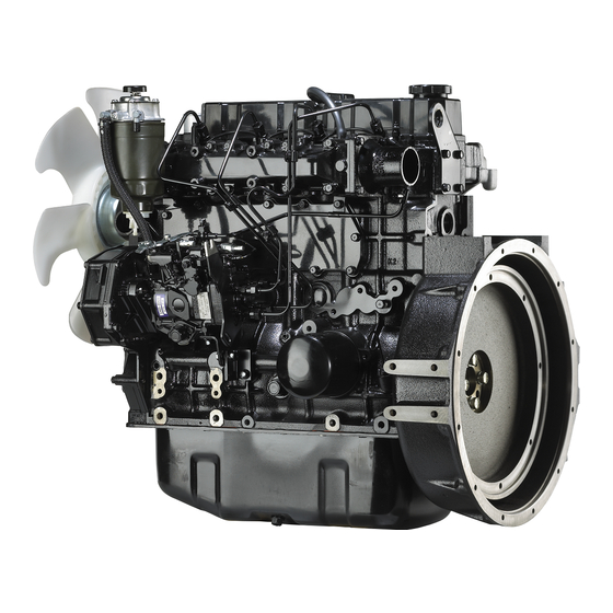
- Page 10 OUTLINE GENERAL [S6S - Standard] Oil filler Hanger Thermostat Hanger Thermoswitch Exhaust manifold Alternator Engine serial number Oil pressure switch Starter V-belt Oil pan REAR FRONT RIGHT SIDE VIEW Inlet manifold Fuel filter Fuel injection nozzle Stop solenoid Air vent screw...
- Page 11 GENERAL OUTLINE [S6S-DT - Standard] Turbo charger Oil filler Oil filler Thermostat Hanger Hanger Thermoswitch Engine serial number Exhaust manifold Alternator Oil pressure switch Starter V-belt Oil pan REAR FRONT RIGHT SIDE VIEW Inlet manifold Fuel filter Governor Stop solenoid...
-
Page 12: Engine Serial Number Location
OUTLINE GENERAL Engine Serial Number Location The engine serial number is located on the side of the crankcase. Engine serial number Engine Model and Application Codes S 4 S - D T S - Manufactured by Sagamihara Machinery Works 4 - Number of cylinders S - Series code D - Direct injection type T - Equipped with turbocharger... -
Page 13: Specifications
GENERAL SPECIFICATIONS GENERAL SPECIFICATIONS Model designation S4S-DT Type Water-cooled, 4-stroke cycle No. of cylinders - arrangement 4 - in line Combustion chamber type Swirl chamber Direct injection Valve mechanism Overhead Cylinder bore x stroke mm [in.] 94 x 120 [3.70 x 4.72] Piston displacement liter [cu in.] 3.331 [203] Compression ratio... - Page 14 SPECIFICATIONS GENERAL Model designation S4S-DT Type Force feed by oil pump Specification Class CD oil (API Service Classification) Engine oil Capacity (engine) liter [U.S. Approx. 10 [2.6] gal} (Oil pan: 9 [2.4], Filter: 1 [0.3]) Type Trochoid Speed ratio to crankshaft 0.74 Oil pump 28.6 [7.6] at 0.3 MPa (3 kgf/cm...
- Page 15 GENERAL SPECIFICATIONS Model designation S4S-DT Type Bosch A Injection pump Diameter of plunger mm 7 [0.276] 9 [0.354] [in.] Type Bosch, piston Feed pump Cam lobe lift mm [in.] 8 [0.315] 9 [0.354] Governor Type Bosch RSV, centrifugal Type of nozzle Bosch throttle Bosch hole No.
- Page 16 SPECIFICATIONS GENERAL Model designation S6S-DT Type Water-cooled, 4-stroke cycle No. of cylinders - arrangement 6 - in line Combustion chamber type Swirl chamber Direct injection Valve mechanism Overhead Cylinder bore x stroke mm [in.] 94 x 120 [3.70 x 4.72] Piston displacement liter [cu in.]...
-
Page 17: Model Designation
GENERAL SPECIFICATIONS Model designation S6S-DT Type Force feed by oil pump API Service Classification Engine oil Refill capacity liter [U.S. Whole system: Approx. 12 liter [3.2 U.S. gal]; gal} Oil pan: 11 liters [2.9 U.S. gal], Filter: 1 liters [0.3 U.S. gal]... - Page 18 SPECIFICATIONS GENERAL Model designation S6S-DT Type Bosch A Injection pump Diameter of plunger mm 7 [0.276] 9 [0.354] [in.] Type Bosch, piston Feed pump Cam lob lift mm [in.] 8 [0.315] 9 [0.354] Governor Type Bosch RSV, centrifugal Type of nozzle...
-
Page 19: Tips On Disassembly And Reassembly
TIPS ON DISASSEMBLY AND GENERAL REASSEMBLY GENERAL TIPS ON DISASSEMBLY AND REASSEMBLY This service manual covers recommended procedures to be followed when servicing diesel engines. It also contains information on special tools required and basic safety precautions. It is the responsibility of service personnel to be familiar with these requirements, precautions and potential hazards and to discuss these points with their foreman or supervisor. -
Page 20: Reassembly
TIPS ON DISASSEMBLY AND REASSEMBLY GENERAL Reassembly Wash all engine parts, except oil seals, O-rings, rubber seals, etc. in cleaning solvent and dry them with compressed air. Use only the correct tools and instruments. Use only good quality lubricating oils and greases. Be sure to apply a coat of oil, grease, or sealant to parts as specified. -
Page 21: Maintenance Standards
MAINTENANCE STANDARDS ENGLISH 21 / 170 Service Manual Mitsubishi SS-Series diesel engines Version 08/2004... -
Page 22: Maintenance Standards Table
MAINTENANCE STANDARDS TABLE MAINTENANCE STANDARDS MAINTENANCE STANDARDS MAINTENANCE STANDARDS TABLE Unit: mm [in.] Assembly Service Nominal Standard Repair Limit Group Inspection Point Limit Remark Value (Standard (Clearance) (Clearance) Clearance) Maximum rpm, (no-load) According to engine Adjust governor setting. specification Minimum rpm, (no-load) 2.9 (30) [427] at 2.6 (27) [384] Compression... - Page 23 MAINTENANCE STANDARDS MAINTENANCE STANDARDS TABLE Assembly Service Nominal Standard Repair Limit Group Inspection Point Limit Remark Value (Standard (Clearance) (Clearance) Clearance) 14.000 to 14.018 14.100 Inside diameter [0.5512 to 0.5519] [0.5551] Clearance between (0.016 to 0.052) (0.080) If it exceeds the repair limit, tappet and bore ([0.0006 to 0.0021]) ([0.0031])
- Page 24 MAINTENANCE STANDARDS TABLE MAINTENANCE STANDARDS Assembly Service Nominal Standard Repair Limit Group Inspection Point Limit Remark Value (Standard (Clearance) (Clearance) Clearance) Inside diameter of rocker 19.010 to 19.030 bushing [0.7484 to 0.7492] [0.75] 18.980 to 19.000 Diameter of rocker shaft [0.7472 to 0.7480] Clearance between (0.010 to 0.050)
- Page 25 MAINTENANCE STANDARDS MAINTENANCE STANDARDS TABLE Assembly Service Nominal Standard Repair Limit Group Inspection Point Limit Remark Value (Standard (Clearance) (Clearance) Clearance) 93.955 to 93.985 93.770 Standard [3.6990 to 3.7002] [3.6917] 0.25 94.205 to 94.235 94.020 [0.0098] [3.7089 to 3.7100] [3.7016] oversize [3.70] 0.50...
- Page 26 A= 46.880 –0.3 +0.004 [0.2646] [0.2450] [1.8457 –0.012 No. 1, 2 (S4S) 53.94 to 53.96 53.90 No. 1, 2, 3 (S6S) [2.13] [2.1236 to 2.1244] [2.1220] No. 3 (S4S) 52.94 to 52.96 52.90 No. 4 (S6S) [2.09] [2.0842 to 2.0850] [2.0827]...
- Page 27 MAINTENANCE STANDARDS MAINTENANCE STANDARDS TABLE Assembly Service Nominal Standard Repair Limit Group Inspection Point Limit Remark Value (Standard (Clearance) (Clearance) Clearance) 17.65 18.14 to 19.12 (180) (185 to 195) Make shim adjustment. Valve opening [2560] [2632 to 2774] Pressure varies by 1 (10) [142] pressure, MPa per 0.1 mm [0.004 in.] (kgf/cm...
- Page 28 MAINTENANCE STANDARDS TABLE MAINTENANCE STANDARDS Assembly Service Nominal Standard Repair Limit Group Inspection Point Limit Remark Value (Standard (Clearance) (Clearance) Clearance) 38.7 38.1 Diameter of commutator [1.52] [1.50] 0.03 Runout of commutator [0.0012] [0.004] 0.4 to 0.6 Depth of commutator [0.016 to 0.2 [0.008] or less mold...
-
Page 29: Tightening Torques
MAINTENANCE STANDARDS TIGHTENING TORQUES MAINTENANCE STANDARDS TIGHTENING TORQUES Important Bolts and Nuts Tightening Torque Thread Width across Remark Description Dia. x Pitch flats, mm (M-thread) N·m kgf·m lbf·ft Cylinder head M12 x 1.75 113 to 123 11.5 to 12.5 83 to 90 Rocker cover M8 x 1.25 10.0 to 13.0... -
Page 30: Standard Bolts
TIGHTENING TORQUES MAINTENANCE STANDARDS Tightening Torque Thread Width across Remark Description Dia. x Pitch flats, mm (M-thread) N·m kgf·m lbf·ft Fuel injection pipe nuts M12 x 1.5 26.5 to 32.4 2.7 to 3.3 19.5 to 23.9 Fuel return pipe nuts M10 x 1.25 17.7 to 21.6 1.8 to 2.2... -
Page 31: Standard Plugs
MAINTENANCE STANDARDS TIGHTENING TORQUES Standard Plugs Torque Thread Diameter For aluminum materials For ferrous materials N·m kgf·m lbf·ft N·m kgf·m lbf·ft NPTF 1/16 4.90 to 7.85 0.5 to 0.8 3.62 to 5.79 7.85 to 11.8 0.8 to 1.2 5.79 to 8.68 PT 1/8 7.85 to 11.8 0.8 to 1.2... -
Page 32: Sealants And Lubricants Table
SEALANTS AND LUBRICANTS TABLE MAINTENANCE STANDARDS MAINTENANCE STANDARDS SEALANTS AND LUBRICANTS TABLE Apply to Mating part Sealant or Lubricant How to Use Oil pan Crankcase Three Bond 1207C Apply to seal. Rear bearing cap seat on crankcase Rear bearing cap Three Bond 1212 Apply to corners before installing cap. - Page 33 SPECIAL TOOLS ENGLISH 33 / 170 Service Manual Mitsubishi SS-Series diesel engines Version 08/2004...
-
Page 34: Special Tools Special Tool List
SPECIAL TOOL LIST SPECIAL TOOLS SPECIAL TOOLS SPECIAL TOOL LIST Tool name Part No. Shape Valve spring pusher 30691-04500 Valve spring removal/installation Valve guide remover 32A91-00300 Valve guide removal Valve guide installer 32A91-00100 Valve guide installation Stem seal installer 32A91-10200 Valve stem installation Valve seat insert Inlet valve:... - Page 35 SPECIAL TOOLS SPECIAL TOOL LIST Tool name Part No. Shape Idler shaft puller MH061077 Idler gear shaft removal Oil seal sleeve installer 30691-13010 Crankshaft rear oil seal sleeve installation Gage adaptor 32A91-01100 Compression pressure (direct injection) measurement Gage adaptor 30691-21100 Compression pressure (swirl chamber) measurement...
- Page 36 SPECIAL TOOL LIST SPECIAL TOOLS Tool name Part No. Shape Camshaft bushing 30691-00010 Camshaft bushing removal/ installer set installation Oil pump bushing 32A91-00400 Oil pump bushing installation installer 36 / 170 ENGLISH Service Manual Mitsubishi SS-Series diesel engines Version 08/2004...
-
Page 37: Overhaul Instructions
OVERHAUL INSTRUCTIONS ENGLISH 37 / 170 Service Manual Mitsubishi SS-Series diesel engines Version 08/2004... -
Page 38: Determination Of Overhaul Timing
DETERMINATION OF OVERHAUL TIMING OVERHAUL INSTRUCTIONS OVERHAUL INSTRUCTIONS DETERMINATION OF OVERHAUL TIMING In most cases the engine should be overhauled when the engine’s compression pressure is low. Other factors that indicate the necessity of engine overhaul are as follows: Decreased power Increased fuel consumption Increased engine oil consumption Increased blow-by gas volume through the... -
Page 39: Testing The Compression Pressure
OVERHAUL INSTRUCTIONS TESTING THE COMPRESSION PRESSURE OVERHAUL INSTRUCTIONS TESTING THE COMPRESSION PRESSURE Remove the injection nozzle from the cylinder head where the compression pressure is to be measured. On the direction injection type engine, attached gage adaptor (32A91–01100) to the cylinder, and connect the compression gage (33391–02100) to the adaptor. - Page 40 TESTING THE COMPRESSION PRESSURE OVERHAUL INSTRUCTIONS ó NOTE Measure the compression pressure with the engine running at 300 rpm. CAUTION a. Measure the compression pressure at regular intervals to obtain correct data. b. The compression pressure will be slightly higher in a new or overhauled engine due to new piston rings, valve seats, etc.
- Page 41 ADJUSTMENTS, BENCH TEST, PERFORMANCE TESTS ENGLISH 41 / 170 Service Manual Mitsubishi SS-Series diesel engines Version 08/2004...
-
Page 42: Adjustments, Bench Test, Performance Tests 10 Adjustments
ADJUSTMENTS, BENCH TEST, ADJUSTMENTS PERFORMANCE TESTS ADJUSTMENTS, BENCH TEST, PERFORMANCE TESTS 10 ADJUSTMENTS 10.1 Valve Clearance Valve clearance should be inspected and adjusted when the engine is cold. Unit: mm [in.] Item Assembly Standard Valve Inlet clearance (cold 0.25 [0.0098] Exhaust setting) Inspection... -
Page 43: Fuel System Bleeding
ADJUSTMENTS, BENCH TEST, PERFORMANCE TESTS ADJUSTMENTS Adjusting Loosen the lock nut of the adjusting screw. Adjust the clearance by turning the screw in either direction to the extent that the gage is slightly gripped between the rocker arm and valve cap. After adjusting the clearance, tighten the lock nut. -
Page 44: Fuel Injection Timing
ADJUSTMENTS, BENCH TEST, ADJUSTMENTS PERFORMANCE TESTS 10.3 Fuel Injection Timing The injection timing varies according to the output, speed and specifications of the engine. Be sure to verify the timing by referring to the specifications. Bringing the No.1 cylinder piston to the top dead center on compression stroke Crankshaft pulley Put socket (58309–73100) on the crankshaft... -
Page 45: No-Load Minimum (Idling) Speed And Maximum Speed Setting
ADJUSTMENTS, BENCH TEST, PERFORMANCE TESTS ADJUSTMENTS Adjusting injecting timing If the injection timing is retarded, move the injection pump toward the crankcase. If the To advance timing is advanced, move the pump away injection timing from the crankcase. To retard injection timing Figure 9... - Page 46 ADJUSTMENTS, BENCH TEST, ADJUSTMENTS PERFORMANCE TESTS Starting engine Pull speed control lever to the high speed side. Operate the starter switch to crank the Speed control lever engine. The engine will fire up at 150 rpm of cranking speed. When the engine fires, hold the engine Low idle speed speed between 800 and 1000 rpm.
- Page 47 ADJUSTMENTS, BENCH TEST, PERFORMANCE TESTS ADJUSTMENTS Setting rack (maximum output) Hold the speed control lever at the position for the indicated output and speed. Under this condition, check to be sure that the engine is running in a steady state. With the engine running in a steady state, adjust the full-load stopper bolt.
- Page 48 ADJUSTMENTS, BENCH TEST, ADJUSTMENTS PERFORMANCE TESTS Determining speed regulation (speed droop) Speed regulation upon removing load Speed regulation upon removing load Run the engine with the speed control lever set at the position for the rated load and speed. Under this condition, remove the load to bring the engine into no-load condition.
-
Page 49: V-Belt Inspection And Adjustment
ADJUSTMENTS, BENCH TEST, PERFORMANCE TESTS ADJUSTMENTS decrease the preload to widen the regulation. One notch corresponds to 1/4 turn of the adjusting screw and to 3 to 5 speed change of the engine speed. Changing the setting of this adjusting screw changes the governor setting (for limiting the maximum speed). -
Page 50: Bench Testing
ADJUSTMENTS, BENCH TEST, BENCH TESTING PERFORMANCE TESTS ADJUSTMENTS, BENCH TEST, PERFORMANCE TESTS 11 BENCH TESTING An overhauled engine should be tested for performance on a dynamometer. This test is also for breaking in the major running parts of the engine. To test the engine, follow the procedures described below: 11.1 Starting Up Inspect the levels in the radiator, oil pan, and fuel... -
Page 51: Bench Testing (Dynamometer) Conditions
ADJUSTMENTS, BENCH TEST, PERFORMANCE TESTS BENCH TESTING 11.3 Bench Testing (Dynamometer) Conditions Step Speed (rpm) Load (PS) Time (min.) 1000 No-load 1500 (According to engine specification) 100% 11.4 Inspection and Adjustments After Bench Testing Adjusting valve clearance Adjusting injection timing Re-tightening external bolts and nuts ENGLISH 51 / 170... -
Page 52: Performance Tests
ADJUSTMENTS, BENCH TEST, PERFORMANCE TESTS PERFORMANCE TESTS ADJUSTMENTS, BENCH TEST, PERFORMANCE TESTS 12 PERFORMANCE TESTS There are various performance test procedures, and here the procedures for “Earth moving machinery Engines, Part 1 : Test code of net power (JIS D 0006- 1)”... - Page 53 ADJUSTMENTS, BENCH TEST, PERFORMANCE TESTS PERFORMANCE TESTS Standard atmospheric conditions Base temperature 298 K (25°C) [77°F] Atmospheric pressure 100 kPa [750 mmHg] Atmospheric vapor pressure 99 kPa [743 mmHg] Calculation of corrected power Multiply the measured brake power or torque by the calculated diesel engine correction factor (see below) to obtained a corrected value.
- Page 54 ADJUSTMENTS, BENCH TEST, PERFORMANCE TESTS PERFORMANCE TESTS Applicable range of engine factor (fm) 37.2 ≤ qc ≤ 65 mg/( -cycle) • qc ≤ 37.2 mg/( -cycle) : fm = 0.2 (Constant) • 65 mg/( -cycle) ≤ qc : fm = 1.2 (Constant) Range of correction equation use The range of correction factor ( α...
-
Page 55: Engine Auxiliaries Removal And Installation
ENGINE AUXILIARIES REMOVAL AND INSTALLATION ENGLISH 55 / 170 Service Manual Mitsubishi SS-Series diesel engines Version 08/2004... -
Page 56: Preparation
ENGINE AUXILIARIES REMOVAL PREPARATION AND INSTALLATION ENGINE AUXILIARIES REMOVAL AND INSTALLATION 13 PREPARATION This section explains the procedures and tips for removal and installation of the auxiliaries - the preliminary process to go through for overhauling the engine. Shut off the fuel supply, and disconnect the starting system from the engine. -
Page 57: Engine Auxiliaries Removal
ENGINE AUXILIARIES REMOVAL AND INSTALLATION ENGINE AUXILIARIES REMOVAL ENGINE AUXILIARIES REMOVAL AND INSTALLATION 14 ENGINE AUXILIARIES Turbocharger REMOVAL Oil pipe Pipe Turbocharger (engines with turbocharger) Disconnect pipe from the turbocharger and inlet manifold. Disconnect oil pipe and drain pipe from the turbocharger. - Page 58 ENGINE AUXILIARIES REMOVAL ENGINE AUXILIARIES REMOVAL AND INSTALLATION Fuel filter Bracket Disconnect fuel pipes and from the fuel filter. Remove fuel filter complete with bracket from Fuel filter the inlet manifold. Fuel pipe Fuel pipe Figure 19 Removing fuel filter Fuel injection pipes Injection pipe Remove pipe clamps and disconnect injection...
- Page 59 ENGINE AUXILIARIES REMOVAL AND INSTALLATION ENGINE AUXILIARIES REMOVAL Fuel injection nozzles (direct injection type) Remove gland, then remove nozzle and gasket from the cylinder head. Nozzle Gland Gasket Figure 22 Removing fuel injection nozzles (direct injection type) Fuel injection nozzles (swirl chamber type) Remove nozzle and gasket.
- Page 60 ENGINE AUXILIARIES REMOVAL ENGINE AUXILIARIES REMOVAL AND INSTALLATION Glow plugs (swirl chamber type) Loosen nuts, then remove connection plate and glow plug. Connection plate Glow plug Figure 25 Removing glow plugs (swirl chamber type) 10. Fuel injection pump Fuel injection pump Remove oil pipe.
- Page 61 ENGINE AUXILIARIES REMOVAL AND INSTALLATION ENGINE AUXILIARIES REMOVAL 12. Oil filter Remove oil filter with a filter wrench. Oil filter Figure 28 Removing oil filter 13. Alternator V-belt Disconnect harness from alternator. Remove Adjusting bolt adjusting bolt. Remove bolts to remove the alternator. Remove V-belt.
- Page 62 ENGINE AUXILIARIES REMOVAL ENGINE AUXILIARIES REMOVAL AND INSTALLATION 15. Starter Disconnect harness from starter. Remove nuts to remove the starter. Starter Figure 31 Removing starter 16. Thermostat Remove water by-pass hose. Remove the bolts that hold thermostat case to Thermostat remove the termostat case.
-
Page 63: Engine Auxiliaries Installation
ENGINE AUXILIARIES REMOVAL AND INSTALLATION ENGINE AUXILIARIES INSTALLATION ENGINE AUXILIARIES REMOVAL AND INSTALLATION 15 ENGINE AUXILIARIES INSTALLATION To install the engine auxiliaries, follow the removal procedures in reverse. After installation, service them as follows: Refill the engine with the recommended oil up to the specified level. - Page 64 ENGINE AUXILIARIES REMOVAL ENGINE AUXILIARIES INSTALLATION AND INSTALLATION 64 / 170 ENGLISH Service Manual Mitsubishi SS-Series diesel engines Version 08/2004...
-
Page 65: Engine Main Parts
ENGINE MAIN PARTS ENGLISH 65 / 170 Service Manual Mitsubishi SS-Series diesel engines Version 08/2004... -
Page 66: Cylinder Heads And Valve Mechanism
CYLINDER HEADS AND VALVE MECHANISM ENGINE MAIN PARTS ENGINE MAIN PARTS 16 CYLINDER HEADS AND VALVE MECHANISM 16.1 Disassembly Replace. Check threads for stripping. Check for wear. Check push rod contact face for wear. Check valve cap contact face for wear. Check oil hole for clogging. - Page 67 CYLINDER HEADS AND VALVE ENGINE MAIN PARTS MECHANISM Snap ring Inlet valve rocker arm Exhaust valve rocker arm Rocker shaft spring 10. Rocker shaft 11. Valve cap 12. Valve pushrod 13. Cylinder head bolt Remove 14 through 19 as an assembly 14.
-
Page 68: Inspection
CYLINDER HEADS AND VALVE MECHANISM ENGINE MAIN PARTS Removing cylinder head Remove the cylinder head bolts. Lift the head off the crankcase. NOTE a. When removing the gasket from the crankcase, be careful not to damage the gasket contact surface of the crankcase. b. - Page 69 CYLINDER HEADS AND VALVE ENGINE MAIN PARTS MECHANISM Unit: mm [in.] Nominal Assembly Repair Item Value Standard Limit 19.010 to Inside diameter 19.030 of rocker [0.7484 to bushings 0.7492] [0.75] 18.980 to Diameter of 19.000 rocker shaft [0.7472 to 0.7480] Clearance 0.010 to between rocker...
- Page 70 CYLINDER HEADS AND VALVE MECHANISM ENGINE MAIN PARTS Unit: mm [in.] Nominal Assembly Repair Item Value Standard Limit 0.065 to Inlet 0.095 0.150 Clearance valve [0.0026 to [0.0059] between 0.0037] valve 0.080 to stem and Exhaust 0.115 0.200 guide valve [0.0032 to [0.0079] 0.0045]...
- Page 71 CYLINDER HEADS AND VALVE ENGINE MAIN PARTS MECHANISM Inspecting valve face Coat the valve face lightly with red lead. Use the Valve lapper to inspect the valve contacts with its seat. If the contact is not uniform, or if the valve is defective or if the service limit is exceeded, repair Valve lapper or replace the valve and valve seat.
- Page 72 CYLINDER HEADS AND VALVE MECHANISM ENGINE MAIN PARTS Refacing valve face If the valve face is badly worn, reface it with a valve refacer. NOTE a. Set a valve refacer to an angle of 30° b. The valve has a stellate facing. This facing will be gone if the valve margin exceeds the service limit.
- Page 73 CYLINDER HEADS AND VALVE ENGINE MAIN PARTS MECHANISM Before installing replacement valve seats in Unit: mm [in.] the cylinder head, measure the bores in the cylinder head for the valve seats. +0.0025 +0.0025 +0.00098 +0.00098 [1.811 [1.457 Inlet valve Exhaust valve seat bore seat bore Figure 50...
- Page 74 CYLINDER HEADS AND VALVE MECHANISM ENGINE MAIN PARTS Using lapping tool, hold the valve against the seat and rotate it only a part of a turn, then raise the valve off the seat, rotating it to a new position. Then press the valve against the seat for another part of a turn.
-
Page 75: Reassembly
CYLINDER HEADS AND VALVE ENGINE MAIN PARTS MECHANISM 11. Measuring valve pushrod deflection Measure the pushrod deflection with a V-block and a dial indicator as shown in the illustration. If the dial indicator reading exceeds the assembly standard, replace the pushrod. Unit: mm [in.] Item Assembly Standard... - Page 76 CYLINDER HEADS AND VALVE MECHANISM ENGINE MAIN PARTS Tap the valve stem top with a soft-faced hammer several times to make sure the valve spring and cotters are properly installed. Figure 59 Installing valve cotters Installing cylinder head Put the gasket on the top of the crankcase, making sure the two dowel pins enter their holes in the gasket.
- Page 77 ENGINE MAIN PARTS MECHANISM Front No. of bolts: 25 Figure 62 Cylinder head bolt tightening sequence (S6S) Reassembling rocker shafts After reassembling the rocker shafts, make sure the rocker arms move smoothly. Figure 63 Reassembling rocker shafts Installing rocker shaft assembly Install the valve caps in position.
- Page 78 CYLINDER HEADS AND VALVE MECHANISM ENGINE MAIN PARTS Adjusting valve clearance Refer to 1.1, Group 5. Figure 65 Adjusting valve clearance 78 / 170 ENGLISH Service Manual Mitsubishi SS-Series diesel engines Version 08/2004...
-
Page 79: Flywheel
ENGINE MAIN PARTS FLYWHEEL ENGINE MAIN PARTS 17 FLYWHEEL 17.1 Disassembly Replace gasket. Check for cracks or Check for worn or defective dowel hole. defective lip. Check for cracks or defective dowel hole. Check ring gear for worn or defective teeth. Check for strippe threads. -
Page 80: Inspection
FLYWHEEL ENGINE MAIN PARTS Removing flywheel Safety bar Remove one of the bolts that hold the flywheel to the crankshaft. Run safety bar (M12 × 1.25) in the hole from which the bolt was removed in Step (a). Remove the remaining flywheel bolts. Remove the flywheel from the crankshaft by pulling it straight. - Page 81 ENGINE MAIN PARTS FLYWHEEL Face runout and circular runout (radial eccentricity) of flywheel Set a dial indicator at the friction (vertical) surface and turn the flywheel one full revolution to check the face runout. Set a dial indicator at the horizontal surface of the pilot bearing bore and turn the flywheel one full revolution to check the circular runout.
-
Page 82: Reassembly
FLYWHEEL ENGINE MAIN PARTS 17.3 Reassembly Installing oil seal (According to engine specification) Apply a thin coat of grease to the oil seal and Apply grease Flywheel install the oil seal to the flywheel housing with an housing installer. Engine side Flywheel side NOTE If the oil seal contact surface of the crankshaft is... - Page 83 ENGINE MAIN PARTS FLYWHEEL CAUTION During installation, signal to each other to avoid personal injury. Service Manual Mitsubishi SS-Series diesel engines ENGLISH 83 / 170 Version 08/2004...
-
Page 84: Damper, Timing Gears And Camshaft
DAMPER, TIMING GEARS AND CAMSHAFT ENGINE MAIN PARTS ENGINE MAIN PARTS 18 DAMPER, TIMING GEARS AND CAMSHAFT 18.1 Disassembly Replace gasket. Check for wear or damage. Check teeth for wear, nicks, burrs or chips. Check for Check keyway and clogged oil bushing for damage hole or wear. - Page 85 Remove 10 through 12 as an assembly 10. Camshaft 11. Camshaft gear 12. Thrust plate 13. Front plate Removing damper (S6S/DT) Install two safety bars (M12 x 1.25) in the rear end of the crankshaft to hold the crankshaft. Remove the damper. WARNING Be to install the safety bars securely.
- Page 86 DAMPER, TIMING GEARS AND CAMSHAFT ENGINE MAIN PARTS Removing timing gear case assembly Remove the timing gear case assembly as shown. CAUTION Do not cause damage to the oil seal. Oil seal Figure 78 Removing timing gear case assembly Measuring backlash and end play Make a record of the backlash and end play measurements to be referred to for reassembly.
- Page 87 DAMPER, TIMING GEARS AND ENGINE MAIN PARTS CAMSHAFT Removing idler gear Remove the thrust plate and remove the gear as shown. Figure 81 Removing idler gear Removing camshaft Turn the crankcase upside down. Position the camshaft gear so that its lightening holes come to top and bottom.
-
Page 88: Inspection
DAMPER, TIMING GEARS AND CAMSHAFT ENGINE MAIN PARTS 18.2 Inspection 18.2.1 Camshaft and camshaft bushings Measuring camshaft end play Measure the camshaft end play as shown in the illustration. If the end play exceeds the service limit, replace the thrust plate. Unit: mm [in.] Assembly Service... - Page 89 Value Standard Limit No. 1, 2 53.94 to 53.96 53.90 (S4S) No. 1, 54 [2.13] [2.1236 to [2.1220] 2, 3 (S6S) 2.1244] 52.94 to 52.96 No. 3 (S4S) 52.90 53 [2.09] [2.0842 to No. 4 (S6S) [2.0827] 2.0850] 0.070 to 0.118 Front and [0.0028 to...
-
Page 90: Timing Gears
DAMPER, TIMING GEARS AND CAMSHAFT ENGINE MAIN PARTS Replacing camshaft bushings Bushing Adaptor Piece Bushing If the clearance between the camshaft journal and bore in the crankcase exceeds the Adaptor +0.019 service limit, refinish the bore to 57H6 ( 3.125 Ra. and install bushings. To replace or install bushings, use camshaft bushings installer set (30691–00010). -
Page 91: Crankshaft Pulley
DAMPER, TIMING GEARS AND ENGINE MAIN PARTS CAMSHAFT Measuring clearance between idler gear bushing and shaft Measuring diagram Measure the inside diameter of the bushing and the diameter of the shaft to determine the clear- ance between the two. If the clearance exceeds the service limit, replace the idler gear or shaft. -
Page 92: Reassembly
DAMPER, TIMING GEARS AND CAMSHAFT ENGINE MAIN PARTS 18.3 Reassembly Installing front plate Put the gasket on the crankcase, making sure the dowels enter the holes in the gasket. Tighten the bolts that hold the front plate to the crankcase to the specified torque. 10.0 to 13.0 N·m Tightening torque for front (1.0 to 1.3 kgf·m) - Page 93 DAMPER, TIMING GEARS AND ENGINE MAIN PARTS CAMSHAFT Installing idler gear Install the idler gear by aligning its matching mark with those on the crankshaft gear, injection pump gear and camshaft gear and install the thrust plate. Tighten the thrust plate mounting bolts to the specified torque.
- Page 94 DAMPER, TIMING GEARS AND CAMSHAFT ENGINE MAIN PARTS Inspecting and adjusting after reassembly Timing gear backlash and end play After installing the timing gears, check the backlash and end play and, if necessary, adjust them. (Refer to 3.2.) Figure 102 Inspecting backlash and end play Inspecting valve timing Top dead center It is not necessary to inspect the valve timing,...
- Page 95 DAMPER, TIMING GEARS AND ENGINE MAIN PARTS CAMSHAFT Top dead center Rotation Inlet valve Exhaust valve Bottom dead center Figure 105 Valve timing diagram (swirl chamber type) Top dead center Rotation Inlet valve Exhaust valve Bottom dead center Figure 106 Valve timing diagram with 3 mm [0.12 in.] clearance added (swirl chamber type) Installing oil seal (if necessary) Apply a small amount of grease to the oil seal and...
- Page 96 DAMPER, TIMING GEARS AND CAMSHAFT ENGINE MAIN PARTS Installing timing gear case Put the gasket on the front plate, making sure the dowels enter their holes in the gasket. Apply oil to the lip of the oil seal. Tighten the bolts that hold the timing gear case to the specified torque.
- Page 97 [354 to 369 lbf·ft] WARNING Figure 111 Installing crankshaft pulley Be on standby to act when the safety bar comes off inadvertently. 12. Installing damper (S6S/–DT) Hold the crankshaft with safety bars and install the damper. Figure 112 Installing damper ENGLISH...
-
Page 98: Pistons, Connecting Rods, Crankshaft, Crankcase And Tappets
PISTONS, CONNECTING RODS, CRANKSHAFT, CRANKCASE AND TAPPETS ENGINE MAIN PARTS ENGINE MAIN PARTS 19 PISTONS, CONNECTING RODS, CRANKSHAFT, CRANKCASE AND TAPPETS 19.1 Disassembly Check for wear of damage. Check for wear, scoring, cracking, damaged Check for fatigue. or widened ring grooves, clogged oil drain holes or carbon deposits. - Page 99 PISTONS, CONNECTING RODS, ENGINE MAIN PARTS CRANKSHAFT, CRANKCASE AND TAPPETS Connecting rod cap Connecting rod bearing Remove 4 through 10 as an assembly. Top compression ring Second compression ring Oil ring Snap ring Piston pin Piston 10. Connecting rod 11. Bearing cap bolt 12.
- Page 100 PISTONS, CONNECTING RODS, CRANKSHAFT, CRANKCASE AND TAPPETS ENGINE MAIN PARTS Removing piston Turn the crankshaft to bring the piston (from which the connecting rod cap has been removed) to top dead center. Put the handle of a hammer on the big-end of the connecting rod and push the piston assembly off the cylinder.
-
Page 101: Inspection
PISTONS, CONNECTING RODS, ENGINE MAIN PARTS CRANKSHAFT, CRANKCASE AND TAPPETS Removing main bearing caps Remove the bolts that hold the cap to the crankcase. Remove the cap with lower main bearing. To remove the rearmost bearing cap, use a puller as shown in the illustration. NOTE When removing the caps, do not cause damage to the bearings. - Page 102 PISTONS, CONNECTING RODS, CRANKSHAFT, CRANKCASE AND TAPPETS ENGINE MAIN PARTS Inside diameter of cylinders Measuring diagram Unit: mm [in.] Measure the inside diameter of the cylinder at the top (ridged portion), middle and bottom, each in two directions parallel and transverse to the crankshaft, as shown in the illustration.
- Page 103 PISTONS, CONNECTING RODS, ENGINE MAIN PARTS CRANKSHAFT, CRANKCASE AND TAPPETS 19.2.2 Pistons and piston rings Measuring diagram Measuring piston diameter Measure the diameter of the piston at skirt in the direction transverse to the piston pin with a micrometer, as shown in the illustration. If the piston is worn beyond the service limit, replace it.
- Page 104 PISTONS, CONNECTING RODS, CRANKSHAFT, CRANKCASE AND TAPPETS ENGINE MAIN PARTS Measuring cut clearance between ends of piston ring Put the piston ring in the gage or a new cylinder sleeve and measure the cut clearance with feeler gages as shown in the illustration. If the clearance exceeds the service limit, replace all piston rings.
- Page 105 PISTONS, CONNECTING RODS, ENGINE MAIN PARTS CRANKSHAFT, CRANKCASE AND TAPPETS Measuring clearance between piston pin and bore Measure the inside diameter of the piston pin bore and the diameter of the pin as shown in the illustration to check the clearance between the piston and pin.
- Page 106 PISTONS, CONNECTING RODS, CRANKSHAFT, CRANKCASE AND TAPPETS ENGINE MAIN PARTS 19.2.3 Connecting rods, connection rod 49.0 to 59.0 N·m bearings and piston pin bushings (5.0 to 6.0 kgf·m) Measuring diagram [36.2 to 43.4 lbf·ft] Clearance between connecting rod bearing and crankpin Measure the diameter of the crankpin and the inside diameter of the connecting rod bearing as...
- Page 107 PISTONS, CONNECTING RODS, ENGINE MAIN PARTS CRANKSHAFT, CRANKCASE AND TAPPETS Unit: mm [in.] Nominal Assembly Service Item Value Standard Limit Inside diameter 30.020 to 30.045 of connecting [1.18] [1.1819 to 1.1829] rod bush Clearance 0.020 to 0.051 0.080 between pin and [0.0008 to 0.0020] [0.0032] bushing...
- Page 108 PISTONS, CONNECTING RODS, CRANKSHAFT, CRANKCASE AND TAPPETS ENGINE MAIN PARTS To check the rod complete with the piston, put the piston on the surface plate, put a round bar identical with the crankpin in diameter in the big end bore and measure the heights A and B of the bar with a dial indicator.
- Page 109 PISTONS, CONNECTING RODS, ENGINE MAIN PARTS CRANKSHAFT, CRANKCASE AND TAPPETS Weight difference between connecting rod Matching mark assemblies When installing the connecting rod, make sure the weight difference of the connecting rod per engine is in the assembly standard. Unit: mm [in.] Assembly Item Standard...
- Page 110 PISTONS, CONNECTING RODS, CRANKSHAFT, CRANKCASE AND TAPPETS ENGINE MAIN PARTS Grinding crankshaft When grinding the crankpins and journals, be sure to produce the same fillet radius as the original one. They should have a hardness of 620 or more in terms of Vickers Hardness Number. If necessary, re-harden the crankpins and journals, and inspect them for cracks by conducting a magnalux (magnetic particle) test.
- Page 111 PISTONS, CONNECTING RODS, ENGINE MAIN PARTS CRANKSHAFT, CRANKCASE AND TAPPETS Crankshaft grinding dimensions for oversize thrust plates Unit: mm [in.] Oversize Oversize Oversize for front or for front Tolerance rear and rear 0.15 31.15 31.30 [0.005 9] [1.2264] [1.2323] +0.039 0.30 31.30 31.45...
- Page 112 PISTONS, CONNECTING RODS, CRANKSHAFT, CRANKCASE AND TAPPETS ENGINE MAIN PARTS Heat a replacement gear up to 100°C [212°F] with a gear heater. Put the gear on the crankshaft with its keyway aligned with the key and tap the end face of the gear with a hammer.
-
Page 113: Main Bearings
PISTONS, CONNECTING RODS, ENGINE MAIN PARTS CRANKSHAFT, CRANKCASE AND TAPPETS The oil seal sleeve will be worn in the course of time. In such a case, replace both the oil seal and sleeve. Oil seal Oil seal sleeve Figure 148 Checking oil seal running surface Removing oil seal sleeve Hold a flat chisel at right angles to the sleeve and cut the sleeve at three places to loosen it,... - Page 114 PISTONS, CONNECTING RODS, CRANKSHAFT, CRANKCASE AND TAPPETS ENGINE MAIN PARTS Clearance between bearing and journal Install the bearings to the crankcase and bearing cap. Tighten the cap to the specified torque. Measure the inside diameter of the bearing in two positions lengthwise and three crosswise as shown in the illustration to take an average.
-
Page 115: Reassembly
PISTONS, CONNECTING RODS, ENGINE MAIN PARTS CRANKSHAFT, CRANKCASE AND TAPPETS 19.3 Reassembly Installing main bearings Install each upper shell of the main bearing to the crankcase so that the bearing lug fit into the notch in the crankcase. The oil hole in the bearing and crankcase will be aligned when the bearing is so installed. - Page 116 PISTONS, CONNECTING RODS, CRANKSHAFT, CRANKCASE AND TAPPETS ENGINE MAIN PARTS Apply soapy water to the side seals and put the seals in the groove in each bearing cap with rounded side toward outside. Push them Crankcase Bearing cap Side seal into position with the blade of a screwdriver or the like, taking care not to bend or twist them.
- Page 117 PISTONS, CONNECTING RODS, ENGINE MAIN PARTS CRANKSHAFT, CRANKCASE AND TAPPETS Assembling piston and connecting rod WEIGHT mark Assemble the piston and the connecting rod with the WEIGHT mark of the piston and the Apply engine oil. MATCHING mark of the rod on the same side. Apply engine oil to the piston pin and insert the pin into position.
- Page 118 PISTONS, CONNECTING RODS, CRANKSHAFT, CRANKCASE AND TAPPETS ENGINE MAIN PARTS Installing piston rings Put the compression rings and oil ring in the No. 1 Top mark ring grooves of the piston with piston ring compression ring pliers (31391–12900). No. 2 NOTE compression ring Install the compression rings on the piston with “R”...
- Page 119 PISTONS, CONNECTING RODS, ENGINE MAIN PARTS CRANKSHAFT, CRANKCASE AND TAPPETS Install the upper half of the connecting rod Tab and groove bearing to the big end of the connecting rod, making sure the locating lug fits into the notch in the rod. Apply engine oil to the bearing. Figure 166 Connecting rod and bearing Inserting pistons Camshaft side...
- Page 120 PISTONS, CONNECTING RODS, CRANKSHAFT, CRANKCASE AND TAPPETS ENGINE MAIN PARTS Turn the crankshaft to bring a crankpin to install the piston and connecting rod assembly top dead center. Using piston installer (34491–00200), put the assembly in the cylinder, with FRONT mark () on the piston toward the front of the engine.
-
Page 121: Inlet And Exhaust System
INLET AND EXHAUST SYSTEM ENGLISH 121 / 170 Service Manual Mitsubishi SS-Series diesel engines Version 08/2004... -
Page 122: Description
DESCRIPTION INLET AND EXHAUST SYSTEM INLET AND EXHAUST SYSTEM 20 DESCRIPTION Turbocharger Muffler Air cleaner Cylinder 122 / 170 ENGLISH Service Manual Mitsubishi SS-Series diesel engines Version 08/2004... -
Page 123: Exhaust Manifold
INLET AND EXHAUST SYSTEM EXHAUST MANIFOLD INLET AND EXHAUST SYSTEM 21 EXHAUST MANIFOLD 21.1 Inspection Check the flanges for cracking. Check the flanges for warpage as shown in the illustration. If the warpage exceeds the assembly standard, repair the flanges. Unit: mm [in.] Assembly Item... - Page 124 EXHAUST MANIFOLD INLET AND EXHAUST SYSTEM 124 / 170 ENGLISH Service Manual Mitsubishi SS-Series diesel engines Version 08/2004...
-
Page 125: Lubrication System
LUBRICATION SYSTEM ENGLISH 125 / 170 Service Manual Mitsubishi SS-Series diesel engines Version 08/2004... -
Page 126: Description
DESCRIPTION LUBRICATION SYSTEM LUBRICATION SYSTEM 22 DESCRIPTION With turbocharger, oil cooler and Turbocharger oil jets Valvemechanism Valve pushrod Oil jet Tappet Oil cooler Camshaft Oil pressure relief valve Main oil gallery Idler gear Fuel injection pump Oil pump Oil pan Safety valve Oil filter Oil straimer... -
Page 127: Oil Pump
LUBRICATION SYSTEM OIL PUMP LUBRICATION SYSTEM 23 OIL PUMP 23.1 Disassembly Replace O-ring Figure 172 Disassembly sequence O-ring Main shaft Inner rotor Outer rotor Pump case 23.2 Inspection Checking clearance between outer rotor and inner rotor Check the clearance with a feeler gage, as shown in the illustration. - Page 128 OIL PUMP LUBRICATION SYSTEM Checking clearance between rotors and cover Check the clearance with feeler gages and straight edge, as shown in the illustration. If the clearance exceeds the service limit, replace the pump assembly. Unit: mm [in.] Assembly Service Item Standard Limit...
- Page 129 LUBRICATION SYSTEM OIL PUMP Checking cearance between main shaft and bushing Measure the diameter of the shaft and the inside diameter of the oil pump bushing in the crankcase to find the clearance between the two. If the clearance exceeds the service limit, replace the bushing or the pump assembly.
-
Page 130: Reassembly
OIL PUMP LUBRICATION SYSTEM 23.3 Reassembly Flush Flush Figure 178 Reassembly sequence 130 / 170 ENGLISH Service Manual Mitsubishi SS-Series diesel engines Version 08/2004... -
Page 131: Oil Filter
LUBRICATION SYSTEM OIL FILTER LUBRICATION SYSTEM 24 OIL FILTER 24.1 Disassembly and Inspection Check for clogging or tears. Replace every 250 service hours. Apply engine oil to gasket when installing filter. Figure 179 Disassembly sequence Filter element Service Manual Mitsubishi SS-Series diesel engines ENGLISH 131 / 170 Version 08/2004... -
Page 132: Oil Cooler (Engine With Oil Cooler)
OIL COOLER (ENGINE WITH OIL COOLER) LUBRICATION SYSTEM LUBRICATION SYSTEM 25 OIL COOLER (ENGINE WITH OIL COOLER) 25.1 Disassembly and Inspection Replace gasket Replace O-ring Check for clogging or damage Replace O-ring Figure 180 Disassembly sequence Cover Element 132 / 170 ENGLISH Service Manual Mitsubishi SS-Series diesel engines Version 08/2004... -
Page 133: Oil Pressure Relief Valve
LUBRICATION SYSTEM OIL PRESSURE RELIEF VALVE LUBRICATION SYSTEM 26 OIL PRESSURE RELIEF VALVE Tightening torque: 49.1 to 53.9 N·m 26.1 Inspection (4.5 to 5.5 kgf·m) [32.5 to 39.8 lbf·ft] Check the valve and valve seat for contact. Check the spring the damage. Measure the opening pressure. -
Page 134: Safety Valve (Engine With Oil Cooler)
SAFETY VALVE (ENGINE WITH OIL COOLER) LUBRICATION SYSTEM LUBRICATION SYSTEM 27 SAFETY VALVE (ENGINE WITH OIL COOLER) 27.1 Inspection Tightening torque: Check the valve and valve seat for contact. 64.0 to74.0 N·m Check the spring for damage. (6.5 to 7.5 kgf·m) [47.0 to 54.2 lbf·ft] Unit: MPa (kgf/cm ) [psi]... -
Page 135: Cooling System
COOLING SYSTEM ENGLISH 135 / 170 Service Manual Mitsubishi SS-Series diesel engines Version 08/2004... -
Page 136: Description
DESCRIPTION COOLING SYSTEM COOLING SYSTEM 28 DESCRIPTION With oil cooler Cylinder head Thermostat Bypass pipe Water pump Water jacket Coolant inlet Oil cooler Cylinder head Thermostat Bypass pipe Water pump Coolant inlet 136 / 170 ENGLISH Service Manual Mitsubishi SS-Series diesel engines Version 08/2004... -
Page 137: Water Pump (According To Engine Specification)
WATER PUMP (ACCORDING TO ENGINE COOLING SYSTEM SPECIFICATION) COOLING SYSTEM 29 WATER PUMP (ACCORDING TO ENGINE SPECIFICATION) 29.1 Inspection Check V-belt grooves for wear or damage. Check fan blades for distortion or cracks. Replace gasket. Check for corrosion Check belts for or cracks. -
Page 138: Thermostat
THERMOSTAT COOLING SYSTEM COOLING SYSTEM 30 THERMOSTAT 30.1 Inspection Remove the thermostat from the engine. Temperature, °C [°F] Hang the thermostat in the jar of water, as shown in the illustration. Thermostat must be below the surface of the water and it must be away from the sides of the jar. -
Page 139: Fuel System
FUEL SYSTEM ENGLISH 139 / 170 Service Manual Mitsubishi SS-Series diesel engines Version 08/2004... -
Page 140: Description
DESCRIPTION FUEL SYSTEM FUEL SYSTEM 31 DESCRIPTION Direct injection type Air vent plug Injection nozzle Fuel filter Return pipe Fuel outlet Injection pump Feed pump Fuel inlet Swirl chamber type Air vent plug Injection nozzle Fuel filter Air vent plug Injection pump Return pipe Fuel inlet... -
Page 141: Fuel Filter (Paper-Element Cartridge Type)
FUEL FILTER (PAPER-ELEMENT FUEL SYSTEM CARTRIDGE TYPE) FUEL SYSTEM 32 FUEL FILTER (PAPER- ELEMENT CARTRIDGE TYPE) 32.1 Disassembly and Inspection Air vent plug Check for cracking or stripped thread. Apply engine oil to packing when installing filter. Check for clogging or tearing. -
Page 142: Injection Nozzles (According To Engine Specification)
INJECTION NOZZLES (ACCORDING TO ENGINE SPECIFICATION) FUEL SYSTEM FUEL SYSTEM 33 INJECTION NOZZLES (ACCORDING TO ENGINE SPECIFICATION) 33.1 Disassembly Retaining nut Direct injection type Nozzle tip Straight pin Tip packing Pressure pin Pressure spring Shims Nozzle body Check for wear. Check for fatigue or squareness. -
Page 143: Inspection
INJECTION NOZZLES (ACCORDING TO FUEL SYSTEM ENGINE SPECIFICATION) 33.2 Inspection Injection pressure (valve opening pressure) Install the injection nozzle on the tester. Slowly operate the tester handle full strokes to bleed (remove) air from the pipe and nozzle. Make a slow increase in pressure by operating the tester handle at a speed of more than one stroke per second while observing the pressure gage. - Page 144 INJECTION NOZZLES (ACCORDING TO ENGINE SPECIFICATION) FUEL SYSTEM To adjust the injection pressure, increase or decrease the amount of shims fitted to the nozzle holder. NOTE 0.1 mm [0.004 in.] thickness of shims will change the injection pressure approximately 1 MPa (10 kgf/cm [142 psi].
- Page 145 INJECTION NOZZLES (ACCORDING TO FUEL SYSTEM ENGINE SPECIFICATION) If the nozzle is bad, remove the tip from the nozzle and wash needle valve and body in clean washing solution. If the nozzle is still bad after the tip has been washed, replace the tip.
-
Page 146: Reassembly
INJECTION NOZZLES (ACCORDING TO ENGINE SPECIFICATION) FUEL SYSTEM 33.3 Reassembly Direct injection type 24.5 to 34.3 N·m (2.5 to 3.5 kgf·m) [18.1 to 25.3 lbf·ft] Tightening torque for nozzle gland: 21.0 to 23.0 N·m (2.0 to 2.4 kgf·m) [14.5 to 17.4 lbf·ft] Figure 194 Reassembly sequence Swirl chamber type Retaining nut... - Page 147 ELECTRICAL SYSTEM ENGLISH 147 / 170 Service Manual Mitsubishi SS-Series diesel engines Version 08/2004...
-
Page 148: Electrical System General
GENERAL ELECTRICAL SYSTEM ELECTRICAL SYSTEM 34 GENERAL 34.1 Wiring diagrams < S4S ETS type stop solenoid > 148 / 170 ENGLISH Service Manual Mitsubishi SS-Series diesel engines Version 08/2004... - Page 149 ELECTRICAL SYSTEM GENERAL < S4S ETR type stop solenoid > Service Manual Mitsubishi SS-Series diesel engines ENGLISH 149 / 170 Version 08/2004...
- Page 150 GENERAL ELECTRICAL SYSTEM < S6S ETR type stop solenoid > 150 / 170 ENGLISH Service Manual Mitsubishi SS-Series diesel engines Version 08/2004...
-
Page 151: Starter
ELECTRICAL SYSTEM STARTER ELECTRICAL SYSTEM 35 STARTER 35.1 Disassembly [12 V - 2.2 kW, 12 V - 3 kW] Surface roughness, grooved wear, worn or damaged gear teeth. Rotation Rotation Buildup of brush dust, uneven wear or sticking in holder. Worn or damaged teeth. -
Page 152: Inspection
STARTER ELECTRICAL SYSTEM 35.2 Inspection Armature Testing for short circuit Place the armature on a growler, and slowly revolve it with a hacksaw blade held above the armature core. The hacksaw blade vibrates against the core when it is above a slot containing a shorted winding. - Page 153 ELECTRICAL SYSTEM STARTER b. Measure the diameter of commutator. If it is smaller than the service limit, replace the armature. Unit: mm [in.] Nominal Service Item value Limit 31.4 12 V - 2.2 kW [1.24] [1.26] Diameter of commutator 38.7 38.1 12 V - 3 kW [1.52]...
- Page 154 STARTER ELECTRICAL SYSTEM Brushes and holders Wear and brushes Brush Measure the brush length and, if it is less than the service limit, replace the brushes. If the brushes are unevenly worn or rough, recondition them with a sandpaper of #300 to #500.
- Page 155 ELECTRICAL SYSTEM STARTER Overrunning clutch Make sure that the pinion shaft turns freely when turned in the direction of driving (clockwise) and it is locked when turned in the opposite direction. If not, replace the overrunning clutch. Figure 207 Checking pinion shaft Pinion shaft thrust clearance The pinion shaft thrust clearance is the play exhibited by the pinion shaft when it is moved in...
-
Page 156: Reassembly
STARTER ELECTRICAL SYSTEM 35.3 Reassembly [12 V - 2.2 kW, 12 V - 3 kW] Apply grease to lever contact surface Apply grease Apply grease Apply grease Figure 209 Reassembly sequence 35.4 Inspection and Testing After Assembly Pinion clearance adjusment If the assembled starter is wired as shown, the pinion will shift and turn slowly. - Page 157 ELECTRICAL SYSTEM STARTER To adjust the clearance, increase or decrease the number of packings fitted to the magnetic switch. Increasing the number of packings decreases the pinion clearance. Unit: mm [in.] Item Assembly Standard 0.5 to 2.0 Pinion clearance [0.020 to 0.079] Pinion clearance NOTE Figure 211 Measuring pinion clearance...
-
Page 158: Alternator
ALTERNATOR ELECTRICAL SYSTEM ELECTRICAL SYSTEM 36 ALTERNATOR 36.1 Disassembly Check slip rings for dirt buildup, burning or other defects. Check oil seal contact surface of shaft for wear. Check for rotation. Check for rotation. Sticking. Figure 214 Disassembly sequence Nut, washer Pulley, spacer Screw Front bracket assembly... -
Page 159: Inspection
ELECTRICAL SYSTEM ALTERNATOR 36.2 Inspection Brushes Replace the brushes if they are worn down to the service limit line. Unit: mm [in.] 18.5 mm Service limit [0.73 in.] Assembly Service Item Standard Limit 5 mm [0.20 in.] [24 V] 12 V - 50 A 18.5 [0.73] 7 [0.28] 7 mm [0.28 in.] [12 V]... - Page 160 ALTERNATOR ELECTRICAL SYSTEM Rectifier Trio diodes Test the resistance between each diode lead wire Heat sink (–) and heat sink. To test, connect the positive (+) lead wire of the tester to the diode and then the negative (–) lead wire of the tester to the diode. If the resistance is infinite in both cases, the diode is open-circuited.
-
Page 161: Reassembly
ELECTRICAL SYSTEM ALTERNATOR 36.3 Reassembly Figure 219 Reassembly sequence Holding brushes for installing rotor Push the brushes into the holder assembly, and hold them by inserting a 2 mm [0.08 in.] diameter wire into the holes in the brushes. Then install the rotor. Remove Brush the wire after installing the rotor. -
Page 162: Glow Plugs
GLOW PLUGS ELECTRICAL SYSTEM ELECTRICAL SYSTEM 37 GLOW PLUGS 37.1 Inspection If the glow plug glows red when the positive (+) wire is connected to the portion A with the portion B grounded, the plug can be used. 11 – 5.5 (DI) (30 sec. rating) Rated voltage –... -
Page 163: Etr Type Stop Solenoid
ELECTRICAL SYSTEM ETR type stop solenoid ELECTRICAL SYSTEM 38 ETR type stop solenoid Idle Connector P/N 30A87-01600 (Counter-Connector P/N 30A87-00600) Full Stop Spring clip Figure 222 38.1 General The energize-to-run (ETR) solenoid controlled engine shutdown system operates as follows: When the starter switch is turned to the "ON" position, the hold coil and the pull coil are energized simultaneously, pulling the stop lever to the "RUN"... -
Page 164: Solenoid Specification
ETR type stop solenoid ELECTRICAL SYSTEM NOTE If the electrical system includes a control timer to stop the engine, the starter switch should be turned in the "OFF" position for at least 10 seconds before making another start attempt in order to reset the control timer automatically. -
Page 165: Inspection
ELECTRICAL SYSTEM ETR type stop solenoid CAUTION To avoid damage to the stop solenoid, do not energize the pull coil for more than 10 seconds. Allow the solenoid to cool down before energizing again. 38.3 Inspection Check the spring: the coil ends should be squared and ground. - Page 166 ETR type stop solenoid ELECTRICAL SYSTEM 166 / 170 ENGLISH Service Manual Mitsubishi SS-Series diesel engines Version 08/2004...
-
Page 167: Workshop Tips
WORKSHOP TIPS ENGLISH 167 / 170 Service Manual Mitsubishi SS-Series diesel engines Version 08/2004... -
Page 168: Basic Recommended Assembly Procedures
BASIC RECOMMENDED ASSEMBLY PROCEDURES WORKSHOP TIPS WORKSHOP TIPS 39 BASIC RECOMMENDED ASSEMBLY PROCEDURES Proper installation of parts is important to the reliable operation of an engine. This section outlines basic recommended procedures, some of which require special tools, devices or work methods. Improper parts installation can result in parts or engine damages. -
Page 169: O-Rings
BASIC RECOMMENDED ASSEMBLY WORKSHOP TIPS PROCEDURES 39.2 O-rings Use an O-ring guide to install an O-ring over stepped parts, splindes, threads, or key way to prevent damage to ring. Apply a smear of grease to the O-ring before installation. Figure 226 O-ring guide 39.3 Bearings When installing a rolling bearing, be sure to push the inner or outer race by which the bearing is... - Page 170 BLANK PAGE 170 / 170 ENGLISH Service Manual Mitsubishi SS-Series diesel engines Version 08/2004...
Need help?
Do you have a question about the S6S and is the answer not in the manual?
Questions and answers
Здравствуйте можно узнать какой зазор клапонов на моторе S6E
The valve clearance for the Mitsubishi Heavy Industries S6S engine is:
- Inlet valve: 0.065 to 0.095 mm (Standard), 0.150 mm (Limit)
- Exhaust valve: 0.080 to 0.115 mm (Standard), 0.200 mm (Limit)
This answer is automatically generated
Регулятор топливного насоса в разрезе
Где находится отметки на шкиве и на передней крышке ВМТ, если можно то подробно