Table of Contents
Advertisement
Operator's manual
GB
+ INSTRUCTIONS FOR PRODUCT DELIVERY . . . Page 3
"Translation of the original Operating Manual"
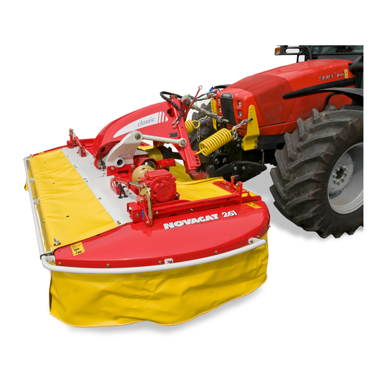
NOVACAT 261 classic
(Type PSM 3752 : + . . 01001)
NOVACAT 301 classic
(Type PSM 3762 : + . . 01001)
NOVACAT 351 classic
(Type PSM 3812 : + . . 01001)
• Disc mower
Nr.
99 3752.GB.80Q.1
Advertisement
Table of Contents


Need help?
Do you have a question about the NOVACAT 261 classic and is the answer not in the manual?
Questions and answers