Table of Contents
Advertisement
Quick Links
Advertisement
Table of Contents

Related Manuals for Wood-mizer PD200G19-S


Summary of Contents for Wood-mizer PD200G19-S
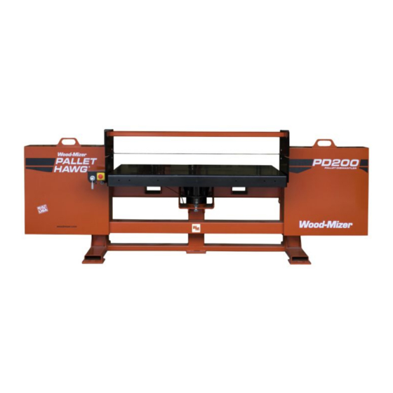
- Page 1 Pallet Dismantler Safety, Operation, Maintenance & Parts Manual PD200G19-S rev. A2.02 PD200G19-SM rev. A2.02 PD200G19-SW rev. A2.02 Safety is our #1 concern! Read and understand all safety information and instructions before oper- ating, setting up or maintaining this machine. Form #2320...
- Page 2 For more information go to www.P65Warnings.ca.gov/wood. Active Patents assigned to Wood-Mizer, LLC Wood-Mizer, LLC has received patents that protect our inventions which are a result of a dedication to research, innovation, development, and design. Learn more at: woodmizer.com/patents ©2021 Wood-Mizer LLC...
-
Page 3: Table Of Contents
Table of Contents Section-Page SECTION 1 INTRODUCTION About this manual...................1-1 Getting service..................1-2 Specifications ..................1-4 Warranty ....................1-5 SECTION 2 GENERA L SAFETY Owner’s Responsibility ............2-1 Safety symbols..................2-1 For models with engines.................2-4 Electrical Lockout Procedures..............2-6 SECTION 3 SETUP AND OPERATION Site Preparation ..................3-1 Onsite setup ....................3-1 Operation ....................3-2 One-person operation ............3-2... - Page 4 Table of Contents Section-Page 5.16 Decals ....................5-23 WMdoc032921 Table of Contents...
-
Page 5: Introduction
Only persons who have read and understood the entire operator's manual should operate the Wood-Mizer Pallet Dismantler Conveyor. The pallet dismantler conveyor is not intended for use by or around children. doc032921... -
Page 6: Getting Service
Getting service Getting service Wood-Mizer is committed to providing you with the latest technology, highest quality equipment, and strongest customer service available on the market today. We continually evaluate our customers’ needs to ensure we’re meeting current wood-processing demands. Your comments and suggestions are welcome. - Page 7 Brazilian Headquarters European Headquarters Serving Brazil Serving Europe, Africa, West Asia Wood-Mizer do Brasil Wood-Mizer Industries Sp z o.o. Rua Dom Pedro 1, No: 205 Bairro: Sao Jose Nagorna 114 Ivoti/RS CEP:93.900-000 62-600 Kolo, Poland Tel: +55 51 9894-6461/ +55 21 8030-3338/ +55 51 Phone: +48.63.26.26.000...
-
Page 8: Specifications
Specifications Specifications Machine Dimensions: Length: 10.5 ft (3.2 m), 11 ft, (3.35 m) 11.5 ft (3.50 m) Width: 5 ft (1.5 m), Height: 4 ft (1.2 m) Material Handling: Standard (S) 60” (1.52 m) Wide (SW) 66” (1.68m) 72 (S72) 72”... -
Page 9: Warranty
Wood-Mizer Limited Product Warranty Wood-Mizer LLC (“Warrantor”), an Indiana corporation with its principal place of business at 8180 West Tenth Street, Indianapolis, IN 46214-2400 USA, warrants to the purchaser (“Purchaser”) that for the time periods specifically stated herein and subject to the terms,... - Page 10 Warranty misuse, negligence, alterations, damage due to overload, abnormal conditions, excessive operation, accident, or lack of performance of normal maintenance services. Several components which are used in the manufacture of the equipment but not manu- factured by Warrantor, such as cant hooks, power plants, laser sights, batteries, tires, and trailer axles have warranties provided by the original equipment manufacturer (written copies available upon request).
- Page 11 Warranty resentation or other affirmation of fact by representatives of Warrantor, whether verbal or in writing, including photographs, brochures, samples, models, or other sales aids, shall constitute a warranty, or any other basis, for any legal action against Warrantor. There are no other representations, promises, agreements, covenants, warranties, guarantees, stip- ulations or conditions, expressed or implied, by Warrantor, except as expressly set forth herein.
- Page 12 Warranty warranty cannot be amended, except in writing, which refers to this warranty that is signed by both Warrantor and Purchaser. Effective: January 1, 2018 © 2013 Wood-Mizer LLC – 8180 West 10 Street, Indianapolis, IN 46214 doc032921...
-
Page 13: General Safety Owner's Responsibility
General Safety Owner’s Responsibility SECTION 2 Genera l Safety Owner’s Responsibility IMPORTANT! It is always the owner's responsibility to comply with all applicable safety instructions, as well as federal, state and local laws, rules and regulations regarding the ownership and oper- ation equipment. - Page 14 General Safety Safety symbols OBSERVE SAFETY INSTRUCTIONS IMPORTANT! Keep children away from the area. Read the entire operator's manual before operating the equip- ment. Take notice of all safety warnings throughout this manual and those posted on the ...
- Page 15 General Safety Safety symbols KEEP HANDS AWAY DANGER! Keep hands 12” away from the blade. Failure to do so will result in death or serious injury. DANGER! Remove power before clearing debris or any other maintenance activity. Failure to do so will result in death or serious injury.
-
Page 16: For Models With Engines
General Safety For models with engines For models with engines HANDLE FUEL/LUBRICANTS SAFELY DANGER! Keep all fuel and lubricants away from children. Failure to do so will result in death or serious injury. DANGER! Never smoke, weld, grind or allow sparks near your engine or storage tanks. - Page 17 General Safety For models with engines WARNING! Battery posts, terminals, and related accessories con- tain lead and lead compounds. Wash hands after handling. Failure to do so may cause death or serious injury. WARNING! Charge the battery in a well ventilated area. Failure to do so may result death or serious injury.
-
Page 18: Electrical Lockout Procedures
General Safety Electrical Lockout Procedures Electrical Lockout Procedures RULES FOR USING LOCKOUT PROCEDURE The equipment shall be locked out to protect against accidental or inadvertent operation when such operation could cause injury to personnel. Do not attempt to operate any switch or valve bearing a lock. - Page 19 General Safety Electrical Lockout Procedures Do not reach into moving blades or feed systems. Allow all coasting parts to come to a complete stop. Electrical power supply and air supply must both be locked out. Where established lockout procedures cannot be used (electrical troubleshooting or ...
- Page 20 General Safety Electrical Lockout Procedures SEQUENCE OF LOCKOUT 1. Notify all affected personnel that servicing or maintenance is required on a machine or equipment and that the machine or equipment must be shut down and locked out to per- form the servicing or maintenance. 2.
- Page 21 General Safety Electrical Lockout Procedures 4. Remove the lockout devices and reenergize the machine or equipment. NOTE: The removal of some forms of blocking may require re-energization of the machine before safe removal. 5. Notify affected personnel that the servicing or maintenance is completed and the machine or equipment is ready for use.
-
Page 22: Setup And Operation
Setup and Operation Site Preparation SECTION 3 SETUP AND OPERATION Site Preparation An outside source of compressed air adjustable from 80-120 psi (5.6-8.4 Kg/cm) is required. WARNING! Have a certified electrician install the power to your machine. Failure to do so may result in death or serious injury. WARNING! Be sure the power supply cables are not a trip hazard. -
Page 23: Operation
Setup and Operation Operation Operation DANGER! Keep hands 12” away from the blade. Failure to do so will result in death or serious injury. WARNING! Do not load pallets greater than 60” (1.5 m). Failure to do so may result in death or serious injury. - Page 24 Setup and Operation One-person operation See Figure 3-1. Stop bolt Tension ratchet handle DM200-03 FIG. 3-1 7. Remove the pass back bars from the table top by unpinning them and slide them out. 8. Momentarily (approximately 15 seconds) run the blade on the drive wheels. 9.
- Page 25 Setup and Operation One-person operation See Figure 3-2. Set table one board thickness + 1/4 inch below blade Air Valve DM201-1 FIG. 3-2 13. Use the air valve to adjust the table approximately one board thickness plus 1/4 inch (6 mm) below the blade.
-
Page 26: Two-Person Operation
Setup and Operation Two-person operation Two-person operation IMPORTANT! Before starting, ensure the blade is tensioned prop- erly. Failure to do so may result in drive wheel tire damage. 1. Tighten the tension by ratcheting the device handle until the pivot arm is touching the stop bolt. - Page 27 Setup and Operation Two-person operation See Figure 3-4. Operator 1 station Pass back bars Operator 2 station DM201-2 FIG. 3-4 6. Use the air valve to adjust the table approximately one board thickness plus1/4 inch (6 mm) below the blade. Air valve controls: Neutral is the 3 o’clock position.
- Page 28 Setup and Operation Two-person operation 9. Operator 1: With the pallet at a slight angle to the blade, push the pallet half way through the blade.(See Figure 3-4.) DANGER! Keep hands 12” away from the blade. Failure to do so will result in death or serious injury.
-
Page 29: Maintenance
Maintenance General maintenance after each use SECTION 4 MAINTENANCE WARNING! Before performing service, lock out the electrical ser- vice as described in section 2.4. Failure to do so could result in death or serious injury. Refer to Online Manuals for electrical schematics. General maintenance after each use 1. -
Page 30: Changing The Blade
Maintenance Changing the blade See Figure 4-1. Locking nuts Tensioner Adjustment bolts DM200-07 FIG. 4-1 3. Loosen the inner (B) while tightening the outer (A) bolt to move the blade TOWARD THE BLADE GUIDE BEARING. 4. Loosen the outer (A) while tightening the inner (B) bolt to move the blade AWAY FROM THE BLADE GUIDE BEARING. - Page 31 Maintenance Changing the blade 2. Release the tension by ratcheting the device until the pivot arm is fully released. See Figure 4-2. Tension ratchet handle DM200-02 FIG. 4-2 3. Removed the used blade. 4. Install the new blade on the center of the drive wheel tires. IMPORTANT! Ensure the blade is positioned as shown below in Figure 4-3.
-
Page 32: Remove The Drive Hub
Maintenance Remove the drive hub 5. Tighten the tension by ratcheting the device handle until the pivot arm is touching the stop bolt. See Figure 4-4. Stop bolt Tension ratchet handle DM200-03 FIG. 4-4 6. Close the wheel covers. 7. Momentarily (approximately 15 seconds) start the blade. 8. - Page 33 Maintenance Remove the drive hub See Figure 4-5. Remove Thread in DM200-08 FIG. 4-5 4. Remove the three bolts in the tapered bushing on the drive shaft. 5. Replace two of the bolts into the treaded holes. 6. Alternate tighten the two bolts until the bushing releases from the wheel flange. The gearbox is now accessible for maintenance.
- Page 34 Maintenance Remove the drive hub doc032921 Maintenance...
-
Page 35: Parts
To Order Parts: From the continental U.S., call 1-800-525-8100 to order parts. Have your customer number, vehicle identification number, and part numbers ready when you call. From other international locations, contact the Wood-Mizer distributor in your area Parts doc032921... - Page 36 Parts How To Use The Parts List for parts. se these torque values on this unit unless otherwise specified. Grade Units SAE 5 SAE 8 Grade Mark Bolt Threads. Units SAE 5 SAE 8 Dia. Per In. in-lbs (Nm) 20 (2.3) in-lbs (Nm) 24 (2.7) 30 (3.4)
-
Page 37: Pallet Dismantler Assembly
Parts Pallet Dismantler Assembly Pallet Dismantler Assembly DM201-4 DESCRIPTION (♦ Indicates Parts Available in Assemblies Only) PART # QTY. Dismantler ASSEMBLY, Pallet PD200 Pallet Dismantler Idle Side (See Section 5.3) Pallet Dismantler Table Parts (See Section 5.4) Pallet Dismantler Drive Side (See Section 5.10) Pallet Engine Parts... -
Page 38: Pallet Dismantler Idle Side
Parts Pallet Dismantler Idle Side Pallet Dismantler Idle Side DM200-13a DESCRIPTION (♦ Indicates Parts Available in Assemblies Only) PART # QTY. Cover Weldment, Dismantler Idle 079979 Nut, 1/2-20 Lug P04646 Tire/Wheel Assembly, ST205/75D15 079939 Shaft Assembly, Dismantler 079921 Hub, 6 lug Dismantler 079941 Shaft, Dismantler Idle Machined 079992... - Page 39 Parts Pallet Dismantler Idle Side DESCRIPTION (♦ Indicates Parts Available in Assemblies Only) PART # QTY. Washer, 1/2 SAE Flat F05011-2 Nut Weldment, Cover 021145 Nut, 1/2-13 Half Nyloc F05010-127 Bolt, 1/2-13x3 Full Thread Hex Head Tap F05008-7 Nut, 1/2-13 Hex F05010-35 Screw, 3/8-16x2 1/2 SHC F05007-24...
-
Page 40: Pallet Dismantler Table Parts
Parts Pallet Dismantler Table Parts Pallet Dismantler Table Parts DM200-21 DESCRIPTION (♦ Indicates Parts Available in Assemblies Only) PART # QTY. Table Weldment, 60" Dismantler 079925 Table Weldment, 66" Dismantler 079925-66 Table Weldment, 72" Dismantler 079925-72 Plate, Dismantler Fence 079953 Bar, Dismantler Passover 079986 Bar, Dismantler Passover 66”... - Page 41 Parts Pallet Dismantler Table Parts DESCRIPTION (♦ Indicates Parts Available in Assemblies Only) PART # QTY. Washer, 1in Split Lock F05011-53 Guard, Dismantler Lower 079966 Guard, Dismantler Lower, 66” 079966-66 Guard, Dismantler Lower, 72” 079966-72 Gusset, 7 3/4 x 7 3/4 079964 Bolt, 3/8-16x1 1/4 Full Thread Hex Head Grade 5 F05007-123...
-
Page 42: Airbag Assembly
Parts Airbag Assembly Airbag Assembly After 10/2020 D 20 DESCRIPTION (♦ Indicates Parts Available in Assemblies Only) PART # QTY. AIRBAG ASSY, DISMANTLER 079970 Airbag, Sleeve Style Spring 079942 Fitting, 1/8NPTx1/4Tube, Straight P03078 doc032921 Parts... -
Page 43: Airbag Assembly
Parts Airbag Assembly Airbag Assembly Before 10/2020 DM200-17 DESCRIPTION (♦ Indicates Parts Available in Assemblies Only) PART # QTY. Airbag Assembly, Dismantler 079970 Nipple, 1/4NPT x 4 Long 016428 Airbag, M-3 Triple Bellow 079942 Bolt, 3/8-16x1 1/4 FT HH Gr5 F05007-123 Washer, 5/16 Split Lock F05011-13... - Page 44 Parts Table Control Assembly Table Control Assembly DM200-20 DESCRIPTION (♦ Indicates Parts Available in Assemblies Only) PART # QTY. Control Assembly, Dismantler Rear 079972 E-Stop Box, 40mm Operator-10A NC 052999 Valve, 3 Position Air 079929 Bracket Weldment, Rear Control 079951 Bolt, 5/16-18x1 Carriage Gr5 f05006-90 Nut, 5/16-18 Nylok Hex...
-
Page 45: Blade Guide Assembly
Parts Blade Guide Assembly Blade Guide Assembly DM200-16 DESCRIPTION (♦ Indicates Parts Available in Assemblies Only) PART # QTY. Blade Guide Assembly, Dismantler 079957 Bearing, R16 Sealed 042360 Mount, B/G Bearing 079954 Block, Dismantler Blade Guide 079955 Spacer, Dismantler Blade Guide 079956 Screw, 3/8-16x1 Zinc &... -
Page 46: Slide Bracket Assembly
Parts Slide Bracket Assembly Slide Bracket Assembly DM200-18 DESCRIPTION (♦ Indicates Parts Available in Assemblies Only) PART # QTY. Bracket Assembly, Dismantler Slide 079985 Bracket, Dismantler Slide 079927 Bolt, 5/16-18x3/4 HHC F05006-5 Bolt, 5/16-18x1 1/4 Hex Head Full Thread Grade 5 F05006-93 Nut, 5/16-18 Nylok Hex F05010-58... -
Page 47: Pallet Dismantler Drive Side
Parts Pallet Dismantler Drive Side 5.10 Pallet Dismantler Drive Side DM201-6 DESCRIPTION (♦ Indicates Parts Available in Assemblies Only) PART # QTY. Cover Weldment, Dismantler, Drive 079980 Nut, 1/2-20 Lug P04646 Tire/Wheel Assembly, ST205/75D15 079939 Nut, 1/2-13 Half Nyloc F05010-127 Nut Weldment, Cover 021145 Bushing, P2x1 5/8... -
Page 48: Fuel Tank
Parts Fuel Tank 5.11 Fuel Tank DM201-5 DESCRIPTION (♦ Indicates Parts Available in Assemblies Only) PART # QTY. Fuel Can Assembly, PD200 110442 Grommet, Slosh Valve 468860A 061253 Slosh Valve 468885A 061252 Gas Cap, 080174AE S-10329 061251 Fitting, Fuel Pick-Up With Shut-Off 074943 Grommet, Shut Off 046881 061250... - Page 49 Parts Fuel Tank DESCRIPTION (♦ Indicates Parts Available in Assemblies Only) PART # QTY. HOSE CLAMP, 7/32IN-5/8IN P649 HOSE, 1/4” ID FUEL P642 HOSE, 1/4” ID FUEL P642 NUT, 3/4-10 HALF NYLOC F05010-122 Tray, PD200 Gas Can 079857 Cover, PD200 Fuel Tank 079858 Washer, 3/8 Flat SAE F05011-3...
-
Page 50: Engine
Parts Engine 5.12 Engine 8 9 10 11 12 13 14 15 16 23 24 25 DM202-7 DESCRIPTION (♦ Indicates Parts Available in Assemblies Only) PART # QTY. Engine Assembly, PD200 079863 Engine, Kohler 19HP CH620-3088 016899 Filter, Kohler Air 006907 Pre Cleaner, Kohler 006931... - Page 51 Parts Engine DESCRIPTION (♦ Indicates Parts Available in Assemblies Only) PART # QTY. Washer, 7/16 Standard Flat F05011-35 Washer, 7/16 Split Lock F05011-48 Bolt, 7/16-14x1 HH Gr5 F05007-145 Spacer, 1 1/8 x 175 x .585 110208 Clutch, Centrifugal 079864 Key, 1/4 x 1 11/16 S04124 Washer, 7/16x1 1/2x1/4 079865...
-
Page 52: Control Panel
Parts Control Panel 5.13 Control Panel 10 11 DM201-9 DESCRIPTION (♦ Indicates Parts Available in Assemblies Only) PART # QTY. Control Assembly, PD200 Gas 079867 Fitting, 1/4 Tube Y 042546 Fitting, 1/4 NPT X 1/4 Air 90 Deg. P21519 Mount, Dismantler Control 079859 Connector, 1/2In 90 Deg Liquid Tight E22722... - Page 53 Parts Control Panel DESCRIPTION (♦ Indicates Parts Available in Assemblies Only) PART # QTY. Fitting, 1/4 NTP Fem. x 1/4 Tb Bulkhead 025235 REDUCER, 1/4NPT TO 1/8NPT P22680 Coupling, 1/8 NPT Male Air P22681 Line, 1/4 Air R01870 12ft Wire, 18AWG Red MTW R01916-03 17ft Shown...
-
Page 54: Engine And Battery Mounts
Parts Engine and Battery Mounts 5.14 Engine and Battery Mounts 6 7 8 9 10 DM201-8 DESCRIPTION (♦ Indicates Parts Available in Assemblies Only) PART # QTY. Guard, PD200 Engine 079854 Nut, 3/8-16 Hex Nyl Lock F05010-10 BOLT, 3/8-16 X 1-1/2 CB F05007-85 Bolt, 3/8-16x1 Gr5 HH F05007-87... - Page 55 Parts Engine and Battery Mounts DESCRIPTION (♦ Indicates Parts Available in Assemblies Only) PART # QTY. Fuse, 150A 32V Mega 052370-150 Nut, #10-24 Keps F05010-14 Strap, LT28 Battery 049129 Washer, 5/16 Standard Flat F05011-16 Bolt, 5/16-18x8 HH Gr5 F05006121 Grommet, Rubber 2 1/2 Dia 085614 Mount Weldment, PD200 Motor 079861...
-
Page 56: Board Catcher (Optional)
Parts Board Catcher (Optional) 5.15 Board Catcher (Optional) DM200BC-01 DESCRIPTION (♦ Indicates Parts Available in Assemblies Only) PART # QTY. Board Catcher, Pallet Dismantler 110233 Nut, 1/2-13 Flanged Hex Nylock F05010-223 Washer, 1/2 SAE Flat F05011-2 Bolt, 1/2-13x1 1/4 HH Gr5 F05008-37 5-22 doc032921... - Page 57 Parts Decals 5.16 Decals TIRE PRESSURE 3.52-3.85 Kg/cm 079664 079665 Located inside the tire housing MF G B Y/ FAB RI QUÉ PAR: WOOD-MIZ ER LLC, 8180 W. 10th St . Indianapolis, IN 46214-2400 U. S. A. 317/271-1542 Or 800/553-0182 Model No.: Seri al No.: Rev.:...
- Page 58 DESCRIPTION (♦ Indicates Parts Available in Assemblies Only) PART # QTY. Decal Kit, Dismantler 079680 Decal, Built In The USA 074008 Decal, Wood-Mizer Quality & Information 079278 Decal, Pallet Scale 079667 Decal, Keep 12" Away 079664 Decal, Eye Warning S12004G...
Need help?
Do you have a question about the PD200G19-S and is the answer not in the manual?
Questions and answers