Table of Contents
Advertisement
Quick Links
Advertisement
Table of Contents

Related Manuals for Wood-mizer HR700


Summary of Contents for Wood-mizer HR700
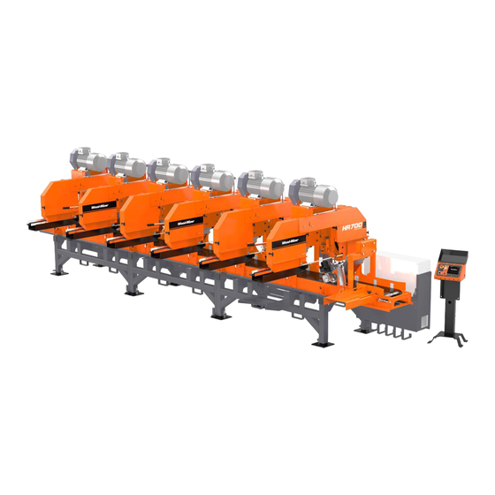
- Page 3 Horizontal Resaw HR700 Safety, Operation, Maintenance & Parts Manual HR700E15S -1/6 rev. A1.01 HR700E20S -1/6 rev. A1.01 HR700E25S -1/6 rev. A1.01 Safety is our #1 concern! Read and understand all safety information and instructions before operating, setting up or maintaining this machine.
-
Page 4: Table Of Contents
Table of Contents Section-Page General Contact Information Branches & Authorized Sales Centers SECTION 1 SAFETY Safety Symbols..................1-1 Safety Instructions ..................1-2 Observe Safety Instructions Wear Safety Clothing Keep Resaw And Area Around Resaw Clean Dispose Of Sawing By-Products Properly Check Resaw Before Operation Keep Persons Away Keep Hands Away Use Proper Maintenance Procedures... - Page 5 Cutting Capacity..................6-6 Blade Motor Specifications ..............6-7 Noise Level.....................6-7 V-Belt Sizes....................6-8 Air Supply Specification ................6-9 Dust Extractor Specifications ..............6-9 SECTION 7 ELECTRICAL INFORMATION Electrical Diagram, 512136-M1 (HR700)..........7-2 Electrical Components, 512136-M1 ..........7-3 Electrical Diagram, 507270-M2 (HR700)..........7-4 Electrical Components, 507270-M2............7-5 Table of Contents SW-07doc0908143...
- Page 6 Table of Contents Section-Page Electrical Diagram, 507270-M3 (HR700) ..........7-6 Electrical Components, 507270-M3 ............7-7 Electrical Components, Power Supply Box (Part #507269) ....7-8 Electrical Component List, HR 700 ...........7-9 Electrical Diagram, Control Box (Part No. 507170)......7-10 7.10 Control Box Electrical Components ............7-11...
-
Page 7: General Contact Information
General Contact Information Getting Service Wood-Mizer is committed to providing you with the latest technology, best quality and strongest customer service available on the market today. We continually evaluate our customers’ needs to ensure we’re meeting current wood-processing demands. Your comments and suggestions are welcome. -
Page 8: Branches & Authorized Sales Centers
Branches & Authorized Sales Centers Branches & Authorized Sales Centers EUROPE UNITED STATES European Headquarters World Headquarters Wood-Mizer Industries Sp. z o.o. Wood-Mizer LLC Nagórna 114, 62-600 Koło, Poland 8180 West 10th Street Tel.: +48-63-26-26-000 Indianapolis,Indiana 46214-2400, Fax: +48-63-27-22-327 www.woodmizer.eu Tel.: +1-317-271-1542... - Page 9 Branches & Authorized Sales Centers CROATIA Krešimir Pregernik ITALY Pasquale Felice SERBIA Dragan Markov Pregimex d.o.o. Wood-Mizer Italia Srl Wood-Mizer Balkan d.o.o. S. Batušiæa 31, 10090 Zagreb Cda. Capoiaccio SN Svetosavska GA 3/3; P. Fah 25 Tel.:/Fax: +3851-38-94-668 86012 Cercemaggiore 23 300 Kikinda Krešimir Pregernik...
- Page 10 Tel.: +49-5883-9880-12 GSM: +49-17-298-55-892 e-mail: KLongmuss@woodmizer.de Subagents: ROMANIA Adrian Echert Regional Manager - Asia DENMARK Brian Jensen SC WOOD-MIZER RO SRL Wood-Mizer Asia Pte Ltd. Arnborgvej 9, 7330 Brande- Fasterholt TRANSILVANIEI Nr. 5 James Wong Tel.: +45-971-88-265 Sibiu, Cisnadie 555300...
-
Page 11: Safety
Safety Safety Symbols SECTION 1 SAFETY Safety Symbols The following symbols and signal words call your attention to instructions concerning your personal safety. Be sure to observe and follow these instructions. DANGER! indicates an imminently hazardous situation which, if not avoided, will result in death or serious injury. WARNING! suggests a potentially hazardous situation which, if not avoided, could result in death or serious injury. -
Page 12: Safety Instructions
Wood-Mizer resaw. All Wood-Mizer resaw owners are encouraged to become thoroughly familiar with these applicable laws and comply with them fully while using the machine. - Page 13 Safety Observe Safety Instructions Safety HRdoc090814...
-
Page 14: Wear Safety Clothing
Safety Wear Safety Clothing Wear Safety Clothing WARNING! Secure all loose clothing and jewelry before operating the resaw. Failure to do so may result in serious injury or death. WARNING! Always wear gloves and eye protection when handling bandsaw blades. Changing blades is safest when done by one person! Keep all other persons away from area when coiling, carrying or changing a blade. -
Page 15: Check Resaw Before Operation
Safety Check Resaw Before Operation Check Resaw Before Operation DANGER! Make sure all guards and covers are in place and secured before operating the resaw. Failure to do so may result in serious injury. Keep Persons Away DANGER! Keep all persons out of the path of moving equipment and lumber when operating the resaw. -
Page 16: Keep Hands Away
Safety Keep Hands Away Keep Hands Away DANGER! Always shut off the blade motor before changing the blade. Failure to do so will result in serious injury. DANGER! Motor components can become very hot during operation. Avoid contact with any part of a hot motor. Contact with hot motor components can cause serious burns. -
Page 17: Use Proper Maintenance Procedures
Safety Use Proper Maintenance Procedures Use Proper Maintenance Procedures DANGER! Make sure all electrical installation, service and/or maintenance work is performed by a qualified electrician and is in accordance with applicable electrical codes. DANGER! Hazardous voltage inside the electric boxes and at the motor can cause shock, burns, or death. -
Page 18: Keep Safety Labels In Good Condition
Safety Keep Safety Labels In Good Condition CAUTION! Always wear gloves when handling the blade. Never grab the blade with bare hands! CAUTION! If the blade breaks during resaw operation, push the EMERGENCY STOP button to stop the blade motor and wait 10 seconds before you open the blade housing cover. - Page 19 Safety Keep Safety Labels In Good Condition See Table 1-1. Pictogram decals used to warn and inform the user about danger in the resaw. TABLE 1-1 Decal View W-M No. Description 096317 CAUTION! Read thoroughly the manual before operating the machine. Observe all safety instructions and rules when operating the resaw.
- Page 20 Safety Keep Safety Labels In Good Condition TABLE 1-1 099221 CAUTION! Keep all persons a safe distance away from work area when operating the machine. 099221 099222 CAUTION! Sawdust outlet. Protect eyes! 096321 Blade movement direction S12004G CAUTION! Always wear safety goggles when operating the resaw! 1-10 HRdoc090814...
- Page 21 Safety Keep Safety Labels In Good Condition TABLE 1-1 S12005G CAUTION! Always wear protective ear muffs when operating the resaw! 501465 CAUTION! Always wear safety boots when operating the resaw 512107 CAUTION! Always wear safety gloves when operating the resaw 501467 Lubrication Point P11789...
- Page 22 Safety Keep Safety Labels In Good Condition TABLE 1-1 P85070 CE sign 099401 Russian safety certification sign 099401 S20097 Motor rotation direction S20097 509025 Blade drive wheel diameter-blade linear speed 509025 257mm 18 m/s 231mm 20 m/s 197mm 24 m/s 505346 Tensioner Valve Handle Placement, TVS TVS 505346...
- Page 23 Safety Keep Safety Labels In Good Condition TABLE 1-1 101176 CAUTION! Compressed air in the system even after electric power disconnection. 101176 513181 Pressure value of the pneumatic system. 6 bar 0.6 MPa 513181 Safety HRdoc090814 1-13...
-
Page 24: Operation
Operation Control Overview SECTION 2 OPERATION Control Overview See Figure 2-1. The control panel includes switches to start and stop the feed track and the saw head. Blade Motor Emergency Stop START/STOP Button Button Emergency Stop Motor/Brake Hour Meter Button Switch Feed Track Switch... - Page 25 Operation Control Overview 3. Feed Track Speed Adjustment The feed track speed switch controls the speed at which the feed track moves. Turn the TRACK FEED switch clockwise to increase the speed, counterclockwise to reduce the speed. 4. Emergency Stop Push the emergency stop button to stop the blades and the track feed motor.
-
Page 26: Resaw Setup
Operation Resaw Setup Resaw Setup The Horizontal Resaw is delivered to the customer place in modules. The HR modules must be mounted together. See Figure 2-2. Attach the base to the additional module (or modules). hr023a 509666_manuals_oper hr023a FIG. 2-2 See Figure 2-3. - Page 27 Operation Resaw Setup additional module (modules) together. Screw, M6x10 Hex Socket Head Cap Washer, 17 (4) M16x160 Bolt (2) M16 Nut (2) M12x40 Bolt (2) FIG. 2-3 Operation MHdoc090814...
- Page 28 Operation Resaw Setup See Figure 2-4. Mount the feed chain drive module. Screw, M6x10 Hex Socket Head Cap Nut, M16 (2) M16x160 Bolt(2) Washer, 17 (4) FIG. 2-4 MHdoc090814 Operation...
- Page 29 Operation Resaw Setup See Figure 2-5. Mount the feed chain and apply proper tension. See Section 4.8 Link the chain using the Chain Tension Adjusting Bolts FIG. 2-5 IMPORTANT! Before stariting to use any HR resaw equipped with return tables, move the control panel and the rear e-stop to the locations shown in the figures 2-7 to 2-12 (depending on the resaw configuration).
- Page 30 Operation Resaw Setup The resaw can’t be operated outdoor when it is raining/snowing and in case of rain/snow the resaw must be stored under roof or indoor. The resaw can be operated in temperature range from -15 C to 40 C (5 F to ...
- Page 31 Operation Resaw Setup 230/400V 50Hz 3 AWG/ 25 62kW at 15kW (E20) 460V 60Hz 71kW at 230/400V 50Hz 1 AWG/ 35 77kW at 15kW (E20) 460V 60Hz 88,5kW at 230/400V 50Hz 0 AWG/ 50 93kW at 15kW (E20) 460V 60Hz 106kW at 230/400V 50Hz 9 AWG/ 6...
-
Page 32: Electrical Requirements (Us Version Only)
Operation Electrical Requirements (US Version Only) See Figure 2-6. Pressure Adjusting Gauge Air Supply Cut-OFF Valve Air Supply Connection FIG. 2-6 Electrical Requirements (US Version Only) DANGER! Make sure all electrical installation, service and/or maintenance work is performed by a qualified electrician and is in accordance with applicable electrical codes. - Page 33 Operation Electrical Requirements (US Version Only) See Table 2-3. The machine FLA required for the resaw is listed below. Power Supply Machine FLA/# of Heads Motor Volts 50/60 380-415 TABLE 2-3 Transformer Required. FLAs include a transformer. Operator’s positions and E-STOP locations are shown in the figures below. ...
- Page 34 Operation Electrical Requirements (US Version Only) 2000kg (4410 lb). The HR modules must be separated before lifting. The resaw is equipped with forklift pockets. Insert the forks into the pockets shown in the figure below. 009a 509666_manual_oper 009a FIG. 2-8 2-11 MHdoc090814 Operation...
-
Page 35: Replacing The Blade
Operation Replacing The Blade Replacing The Blade DANGER! Always shut off the resaw motor before changing the blade. Failure to do so may result in serious injury. WARNING! Always wear gloves and eye protection whenever handling bandsaw blades. Changing blades is safest when done by one person! Keep all other persons away from work area when changing blades. - Page 36 Operation Replacing The Blade blade housing. Lift the blade out of the blade housing. rs_002a HR500-5_MANUALS Install a new blade around the two blade wheels so that the teeth located between the blade guide assemblies point to the drive side of the machine. Make sure the teeth are pointing the correct direction.
-
Page 37: Tensioning The Blade
Operation Tensioning The Blade Tensioning The Blade See Figure 2-9. Place the provided handle in the blade tensioner socket and secure with a screw. Set the tensioner valve to the ”1” position. Move the tensioner handle up and down to tension the blade. Depending on the installed blade type, tension the blade to the value shown on the decal located below the blade tension valve. -
Page 38: Tracking The Blade
Operation Tracking The Blade Tracking The Blade 1. Open the blade housing cover. 2. Turn the key switch to the ”H” position. 3. Manually spin one of the blade wheels until the blade positions itself on the blade wheels. 4. Check that the blade is properly positioned on the blade wheels. See Figure 2-10. -
Page 39: Saw Head Height Adjustment
Operation Saw Head Height Adjustment CAUTION! Make sure all guards and covers are in place and secured before operating or towing the resaw. Failure to do so may result in serious injury. Be sure the blade housing cover is in place and secured. NOTE: After aligning the blade on the wheels, always check the blade guide spacing and location. - Page 40 Operation Saw Head Height Adjustment head. Saw Head Height Indicator FIG. 2-12 NOTE: When adjusting the saw head height lower than 20mm, adjust the blade guide arm so that it does not touch the feed chain. 2-17 MHdoc090814 Operation...
- Page 41 Operation Saw Head Height Adjustment See Figure 2-13. <20mm FIG. 2-13 Operation MHdoc090814 2-18...
-
Page 42: Tilt
Operation Tilt Tilt See Figure 2-14. The saw head may be tilted to produce siding. Loosen the locking bolt. Turn the tilt adjustment screw clockwise to tilt the saw head upward or counterclockwise to tilt the saw head downward. rs_008 Tilt Adjustment Screw Tilt Adjustment Screw Locking Bolt... -
Page 43: Guide Fence Adjustment
Operation Guide Fence Adjustment Guide Fence Adjustment See Figure 2-15. Loosen the wing nuts. Move the guide fence to the desired cant width. Wing Nut FIG. 2-15 Operation MHdoc090814 2-20... -
Page 44: Blade Guide Arm Adjustment
Operation Blade Guide Arm Adjustment Blade Guide Arm Adjustment The outside blade guide arm can be adjusted in or out depending on the width of the material to be cut. The arm should be adjusted about 25 mm (1”) wider than the material to be cut. -
Page 45: Machine Start
Operation Machine Start 2.10 Machine Start DANGER! Before starting the resaw, perform these steps to avoid injury and/or damage to the equipment: Close the blade housing cover and replace any guards removed for service. Check the feed track and remove all loose objects such as tools, wood, etc. ... - Page 46 Operation Machine Start To stop the blade motors, press the STOP button shown in the figure above. The blade motor also may be stopped by pushing either of the emergency stop buttons. If either of the emergency stops has been used to stop the blade motor, rotate the switch clockwise before restarting the saw head.
- Page 47 Operation Machine Start See Figure 2-19. The speed at which the feed track moves is adjustable. The feed track FIG. 2-19 speed switch, located on the control panel, allows the operator to adjust the feed rate from 0 to ca. 25 m (82 ft) per minute. Turn the switch clockwise to increase the feed rate, counterclockwise to slow the feed rate down.
- Page 48 Operation Machine Start hard will require slower feed rates. Sharpness of blades. Dull or improperly sharpened blades will require slower feed rates than sharp and properly maintained blades. Off-bearing capability. Your ability to feed end-to-end will also determine what ...
-
Page 49: Water Lube Operation
Operation Water Lube Operation 2.11 Water Lube Operation Standard Lube System (Supplied from a Water Supply Network) The Water Lube System keeps the blade clean. It is supplied from a water-pipe network (minimum pressure 0.35bar [0,05MPa], maximum 6bar [0.6MPa]). Water flows though a hose, a solenoid and a manual valve to the blade guide where the blade enters the log. - Page 50 Operation Standard Lube System (Supplied from a Water Supply Network) flow. FIG. 2-21 2-27 MHdoc090814 Operation...
-
Page 51: Optional Lube System (Supplied From Water Tanks)
Operation Optional Lube System (Supplied from Water Tanks) Optional Lube System (Supplied from Water Tanks) See Figure 2-22. The Water Lube System keeps the blade clean. Water flows from a 5-gallon (18.9 liter) bottle through a hose to the blade guide where the blade enters the log. -
Page 52: Operation Procedure
Operation Operation Procedure 2.12 Operation Procedure 1. Install a blade if necessary. WARNING! Always wear gloves and eye protection when handling bandsaw blades. Changing blades is safest when done by one person! Keep all other persons away from area when coiling, carrying or changing a blade. Failure to do so may result in serious injury. - Page 53 Operation Operation Procedure DANGER! Always be aware of and take proper protective measures against rotating shafts, pulleys, fans, etc. Always stay a safe distance from rotating members and make sure that loose clothing or long hair does not engage rotating members resulting in possible injury.
-
Page 54: Multisetworks Operation (Optional Equipment)
MultiSETWORKS OPERATION (Optional Equipment) General Information SECTION 3 MULTISETWORKS OPERATION (OPTIONAL EQUIPMENT) General Information A new Multisetworks has been designed to automatically set the saw heads at any required height. It can be mounted on the HR500 resaw as optional equipment together with the electric up/down drive. The Multisetworks can work in two modes: MANUAL (each saw head can be set by the operator separately) and X-BOARD (the saw heads are set automatically according to pre-selected board thickness values - including blade kerf loss). - Page 55 MultiSETWORKS OPERATION (Optional Equipment) Start-up Settings of the Multisetworks When the Multisetworks is started for the first time, the Diagnostic/Tune screen is displayed. See Pic. 3-2. PIC. 3-2 TUNE: activates the automatic procedure of setting up/down movement parameters. DIAGNOSTIC I/O: used to move to the diagnostic screen. ...
-
Page 56: Tuning
MultiSETWORKS OPERATION (Optional Equipment) Start-up Settings of the Multisetworks 3.2.1 Tuning After starting the tuning procedure, the CALIBRATION screen is displayed. See Pic. 3-3. PIC. 3-3 Measure the height of each saw head and enter these values in the fields: Head1, Head2, etc. Then press ACCEPT. - Page 57 MultiSETWORKS OPERATION (Optional Equipment) Start-up Settings of the Multisetworks See Pic. 3-4. PIC. 3-4 The values in each HEAD window represent the current numbers of encoder revolutions. The arrows show if the up/down motor contactors are being activated. Be sure that each saw head is set approximately in the middle of the distance between the upper and lower travel limits.
-
Page 58: Kerf
MultiSETWORKS OPERATION (Optional Equipment) Start-up Settings of the Multisetworks 3.2.2 Kerf It is necessary to enter the kerf value to allow the Multisetworks to work properly. Choose DIAGNOSTIC on the CHOOSE MODE screen. See Pic. 3-5. PIC. 3-5 Then enter the DIAGNOSTIC I/O screen shown below. Multisetworkdoc090814 MultiSETWORKS OPERATION (Optional... - Page 59 MultiSETWORKS OPERATION (Optional Equipment) Start-up Settings of the Multisetworks See Pic. 3-6. PIC. 3-6 The current number of encoder revolutions for each saw head is displayed on this screen (not saw head height). You can manually move each saw head up or down using the corresponding arrows. To change the kerf value, press the KERF key.
-
Page 60: Manual Mode
MultiSETWORKS OPERATION (Optional Equipment) Manual Mode Manual Mode After selecting the MANUAL mode in the main window, the screen shown below will be displayed. See Pic. 3-7. PIC. 3-7 On this screen you can see the current blade height value for each saw head (REAL values) and the target height values that can be changed by the operator. - Page 61 MultiSETWORKS OPERATION (Optional Equipment) Manual Mode See Pic. 3-8. PIC. 3-8 MultiSETWORKS OPERATION (Optional Equipment)Multisetworkdoc090814...
-
Page 62: X-Board Mode
MultiSETWORKS OPERATION (Optional Equipment) X-board Mode X-Board Mode After choosing the X-Board mode in the main window, the following screen will be displayed. See Pic. 3-9. PIC. 3-9 The X-Board screen includes a list of all active saw heads (on the left side) and board thickness values preset for each saw head (on the right side). - Page 63 MultiSETWORKS OPERATION (Optional Equipment) X-board Mode See Pic. 3-10. Feed Direction 50mm 50mm 50mm 50mm 100mm 100mm PIC. 3-10 MultiSETWORKS OPERATION (Optional Equipment)Multisetworkdoc090814 3-10...
-
Page 64: Diagnostic Mode
MultiSETWORKS OPERATION (Optional Equipment) Diagnostic Mode Diagnostic Mode After choosing the Diagnostic mode in the main window, the following screen is displayed. See Pic. 3-11. PIC. 3-11 On the DIAGNOSTIC/TUNE screen, select the DIAGNOSTIC I/O mode. The screen shown below will appear. -
Page 65: Errors
MultiSETWORKS OPERATION (Optional Equipment) Errors In the windows HEAD1, HEAD2, etc. the current encoder readings are shown. You can move each saw head up and down using the up/down arrows. When the saw head is being moved, its encoder reading should be changing. - Page 66 MultiSETWORKS OPERATION (Optional Equipment) Errors encoder and limit switches and the motor switch. Then choose INIT in the DIAGNOSTIC I/O window and perform the tuning procedure. Motor Switch - Head 1 or 2 (3 or 4, 5 or 6) Tripped. If this error occurs, check the motor ...
- Page 67 MultiSETWORKS OPERATION (Optional Equipment) Errors See Pic. 3-15. PIC. 3-15 Incorrect up/down movement direction. This error may be caused by improper connection of the encoder or up/down motor. Enter the Diagnostic mode. Check if the saw head is moving up when you press the UP arrow and down when you press the DOWN arrow.
-
Page 68: Maintenance
MAINTENANCE Wear Life SECTION 4 MAINTENANCE This section lists the maintenance procedures that need to be performed. WARNING! Disconnect and lock out power supply before servicing, cleaning and doing maintenance to the saw! Failure to do so may result in serious injury. This symbol identifies the interval (hours of operation) at which each maintenance procedure should be performed. -
Page 69: Blade Guides
MAINTENANCE Blade Guides Blade Guides 1. Check the rollers for performance and wear every blade change. Make sure the rollers are clean and spinning freely. If not, rebuild them. Replace any rollers which have worn smooth or have become cone shaped. See the Parts manual for blade guide rebuild kits and complete roller assemblies. -
Page 70: Miscellaneous Lubrication
MAINTENANCE Miscellaneous Lubrication Miscellaneous Lubrication 1. Apply a thin film of a lithium grease to the blade guide arm to help prevent it from rusting. 2. Lubricate the feed track chain with an easily penetrating oil such as WD-40. CAUTION! Never apply grease to the feed track chain. -
Page 71: Drive Belt Adjustment
MAINTENANCE Drive Belt Adjustment Drive Belt Adjustment WARNING! Do not for any reason adjust the drive belt with the motor running. Doing so may result in serious injury. See Table 4-2. Check the drive belt tension after the first 20 hours, and every 50 hours thereafter. - Page 72 MAINTENANCE Drive Belt Adjustment 4. Tighten the four motor mounting bolts. Left Adjust- ment Bolt Right Adjust- ment Bolt Motor Mounting Bolts (4) FIG. 4-2 Periodically check the belt for wear. Replace if damaged or worn. See Figure 4-3. Keep the motor and drive pulleys aligned to prevent premature belt wear. To align the motor pulley to the drive pulley, loosen the set screw in the motor pulley groove and slide the motor pulley on the shaft until it is in line with the drive pulley.
- Page 73 MAINTENANCE Drive Belt Adjustment After performing the alignment, make sure the drive belt tension has not been changed. rs_023 FIG. 4-4 MAINTENANCE 25doc090814...
-
Page 74: Feed Track Chain Tension
MAINTENANCE Feed Track Chain Tension Feed Track Chain Tension See Figure 4-5. If necessary, use the adjustment bolts shown below to adjust the feed track chain tension. NOTE: The bolts must be adjusted evenly. See Figure 4-6. Track Chain Tension Adjustment Bolt FIG. -
Page 75: Up/Down System
MAINTENANCE Up/Down System Up/Down System 1. Lubricate the two acme screws, shown below, with a lithium grease every fifty hours of operation, but at least once a week. See Figure 4-8. Blade Height Adjust- ment Screw Saw Head Tilt Adjust- ment Screw FIG. -
Page 76: End Of The Life Cycle
MAINTENANCE End of the life cycle Remove the blades and store them well lubricated in above zero temperature. Loosen the motor belt tension. Spray a thin layer of anti-rust coating (such as P.D.R.P) onto the places not protected against rusting. -
Page 77: Safety Devices Inspection
MAINTENANCE Safety Devices Inspection 4.12 Safety Devices Inspection HR Safety Devices Inspection Before beginning a shift, the following safety devices of the HR resaw should always be checked: E-STOP button circuit - control box E-STOP button circuit - frame ... - Page 78 MAINTENANCE Safety Devices Inspection 2. Frame E-STOP circuit inspection Start the main motor; Push the E-STOP button located on the machine frame. The motor should stop. It should not be possible to restart the motor until the E-STOP is released. Frame E-STOP Button...
-
Page 79: Alignment
SECTION 5 ALIGNMENT Alignment Procedures The Wood-Mizer resaw is factory aligned. This section includes instructions on how to realign the resaw completely. Be scrupulous when performing all alignment steps as resaw alignment determines the accuracy of your cuts. The alignment procedure should be performed approximately every 1500 hours of operation. -
Page 80: Blade Installation And Tracking
Alignment Blade Installation And Tracking Blade Installation And Tracking See Figure 5-1. Install a blade and apply the proper tension as shown below. Section 2.4 Blade Tension Indicator Blade Tension Handle Cant Control TVS 505346 FIG. 5-1 1. Turn the key switch to the "H" position. 2. - Page 81 Alignment Blade Installation And Tracking [0.04"]). Do not let the teeth ride on the belt. SM0044D 3.0 mm (0.12”) ± 1 mm (0.04”) 4.5 mm (0.18”) 1 1/4" ± 1 mm (0.04”) Blade 1 1/2" Blade FIG. 5-2 To adjust where the blade travels on the idle-side blade wheel, use the cant control shown in Figure 5-7.
-
Page 82: Blade Wheel Alignment
Alignment Blade Wheel Alignment Blade Wheel Alignment The blade wheels should be adjusted so they are level in the vertical and horizontal planes. If the blade wheels are tilted up or down, the blade will want to travel in the tilted direction. - Page 83 Alignment Blade Wheel Alignment See Figure 5-4. Use the vertical adjustment screws (marked with the blue and yellow arrows in the figure below) to adjust the drive-side blade wheel. Before adjusting the wheel, loosen the drive belt using the adjustment bolts marked with the orange arrows in the figure.
- Page 84 Alignment Blade Wheel Alignment 4. Recheck the vertical tilt of the drive-side blade wheel with the blade guide alignment tool. Readjust the blade wheel as necessary until the front and rear of the tool are the same distance from the feed track (± 1.0 mm (0.04”)). 5.
- Page 85 Alignment Blade Wheel Alignment 8. Check the position of the blade on the idle-side blade wheel. See Figure 5-6. The horizontal tilt of the blade wheel should be adjusted so that the gullet of an 1-1/4" blade is 3.0 mm out from the front edge of the wheel (± 1.0 mm (0.04”)). 150060 3.0 mm (0.12”) ±...
- Page 86 Alignment Blade Wheel Alignment 9. Check the position of the blade on the drive-side blade wheel. The blade should be positioned on the wheel as described for the idle-side blade wheel. Adjust the drive-side blade wheel if necessary. See Figure 5-8. Use the horizontal adjustment screws (marked with the blue and yellow arrows in the figure below) to adjust the drive-side blade wheel.
-
Page 87: Saw Head Adjustment
Alignment Saw Head Adjustment Saw Head Adjustment See Figure 5-9. The saw head should be set perpendicularly to the vertical mast. Using the two sets of adjustment screws in the mast slide pads, you can adjust the saw head in relation to the mast. -
Page 88: Blade Guide Arm Vertical Adjustment
Alignment Blade Guide Arm Vertical Adjustment Blade Guide Arm Vertical Adjustment 1. Adjust the blade guide arm out to within 1/2" (15 mm) of full open. 2. Measure the distance from the top surface of the feed track to the arm. See Figure 5-10. -
Page 89: Blade Guide Arm Horizontal Adjustment
Alignment Blade Guide Arm Horizontal Adjustment To adjust the rollers, locate the cam bolt inside the housing and turn until the arm is lowered or raised as needed. Recheck the arm in both, open and closed positions. Repeat adjustments until the arm is the same distance from the track feed in the open and closed position. - Page 90 Alignment Blade Guide Arm Horizontal Adjustment See Figure 5-12. Adjustment Nuts Adjustment Nuts SM0066 FIG. 5-12 4. Adjusting the outside two rollers inward will cause the flange to move away from the blade. 5. Adjusting the two outside rollers outward will cause the flange to move toward the blade. 6.
-
Page 91: Aligning The Blade Guides
Aligning the Blade Guides Aligning the Blade Guides Each Wood-Mizer resaw has two blade guide assemblies that help the blade maintain a straight cut. The two blade guide assemblies are positioned on the cutting head to guide the blade on each side of the material being cut. -
Page 92: Blade Deflection
Alignment Blade Deflection Blade Deflection Perform the following steps to achieve proper blade deflection with the blade guides. 1. Raise the saw head until the blade is 200 mm (7.9”) above the feed track. Measure the actual distance with a tape from the top of the track to the bottom of the blade. 2. -
Page 93: Blade Guide Vertical Tilt Adjustment
Alignment Blade Guide Vertical Tilt Adjustment Blade Guide Vertical Tilt Adjustment Check that the blade guide does not tilt the blade up or down. A Blade Guide Alignment Tool (BGAT) is provided to help you measure the vertical tilt of the blade. 1. - Page 94 Alignment Blade Guide Vertical Tilt Adjustment recheck the tilt of the blade. Loosen jam nuts and turn screws to tilt roller up or down SM0070 FIG. 5-15 5. Measure the distance from the bottom of the tool to the top of the feed track chain at the rear end of the tool.
-
Page 95: Blade Guide Spacing
Alignment Blade Guide Spacing 5.10 Blade Guide Spacing HINT: When adjusting the blade guide spacing, loosen the top set screw and one side set screw only. This will ensure horizontal and vertical tilt adjustments are maintained when the set screws are retightened. 1. -
Page 96: Blade Guide Horizontal Tilt Adjustment
6. Use the side set screws to adjust the horizontal tilt of the roller. 7. Repeat steps 3-7 for the inner blade guide roller. NOTE: Once the blade guides have been adjusted, any cutting variances are most likely caused by the blade. See the Wood-Mizer® Blade Handbook, Form #600. 5-18 MHdoc090814... -
Page 97: Blade Height Scale Adjustment
Alignment Blade Height Scale Adjustment 5.12 Blade Height Scale Adjustment After the entire resaw has been aligned and all adjustments have been made, check that the blade height scale indicates the true distance from the blade to the feed track chain. 1. -
Page 98: Specifications
Specifications Overall Dimensions SECTION 6 SPECIFICATIONS Overall Dimensions See Figure 6-1. The major dimensions of the resaw are shown below (all dimensions are in millimeters). Basic Module Feed Drive Module 007c 007c 509666_manual_oper 2nd and 3rd Module FIG. 6-1 MHdoc090814 Specifications... - Page 99 Specifications Overall Dimensions See Figure 6-2. The major dimensions of the resaw are shown below, with CE version (all dimensions are in millimeters). FIG. 6-2 Specifications MHdoc090814...
- Page 100 Overall Dimensions See Table 6-1. The overall dimensions of the resaw are listed in the table below. Weight 2530kg (5577lb) (complete HR700-2) 2400 kg (5291 lb) (base 2-head module) 1800 kg (3968 lb) (2-head extension) 130 kg (286lb) (Chain Feed Drive) Height 2133 mm ( 84”) (to top of the mast)
- Page 101 Specifications Overall Dimensions See Figure 6-4. See the figure below for the major dimensions of the Cross Roller Table (SLPCRT). (47") (29") FIG. 6-4 Specifications MHdoc090814...
- Page 102 Specifications Overall Dimensions See Figure 6-5. The figure below shows locations of the resaw legs. FIG. 6-5 MHdoc090814 Specifications...
-
Page 103: Cutting Capacity
400 mm (15 3/4”) matic up/down system) TABLE 6-2 See Table 6-3. Wood-Mizer offers three types of blades to provide efficient sawing. The type of wood you saw should determine which blade you choose for optimum performance. Recommended Blade Type... -
Page 104: Blade Motor Specifications
Specifications Blade Motor Specifications Blade Motor Specifications See Table 6-4. See the table below for blade motor specifications for your resaw model. Motor Type Manufacturer Model Power Other Specifications E15 Electric EMA-ELFA Pssg 11kW 400 V/50Hz; 23,2 Amp; 132M-4A-HM 1450 r.p.m. E20 Electric EMA-ELFA 2SIE-160 L4 H... -
Page 105: V-Belt Sizes
Specifications V-Belt Sizes V-Belt Sizes See Table 6-6. Belt sizes for the resaw are shown. Belt Description Belt Size Wood-Mizer Part No. Drive Belt 3-B/HB 2240 088993 Drive Belt 507311 Blade Wheel Belt B72.5 017922 TABLE 6-6 Specifications MHdoc090814... -
Page 106: Air Supply Specification
Air Supply Specification Air Supply Specification See the table below for air supply specifications: Air Supply Pressure HR700 Min. 6 bar (87 psi) TABLE 6-6 Dust Extractor Specifications See Table 6-7. Specifications of the dust extractors used on the resaw for each saw head are listed below. -
Page 107: Electrical Information
Electrical Information SECTION 7 ELECTRICAL INFORMATION Specifications MHdoc090814... -
Page 108: Electrical Diagram, 512136-M1 (Hr700)
Electrical Information Electrical Diagram, 512136-M1 (HR700) Electrical Diagram, 512136-M1 (HR700) 1L3-X1 FIG. 7-1 MHdoc090814 Specifications... -
Page 109: Electrical Components, 512136-M1
Electrical Information Electrical Components, 512136-M1 Electrical Components, 512136-M1 Ref. Symbol Description Manufacturer Wood-Mizer Part No. Switch, INTERPACT INS160 3P Disconnect 091552 SCHNEIDER ELECTRIC F1, F2 SCHNEIDER ELECTRIC 090436 Circuit Breaker, GV3ME40 Motor (E20/E25) 1M, 2M, 4M, Contactor, LC1 D25 BD... -
Page 110: Electrical Diagram, 507270-M2 (Hr700)
Electrical Information Electrical Diagram, 507270-M2 (HR700) Electrical Diagram, 507270-M2 (HR700) FIG. 7-2 MHdoc090814 Specifications... -
Page 111: Electrical Components, 507270-M2
Electrical Information Electrical Components, 507270-M2 Electrical Components, 507270-M2 Symbol Description Manufacturer Wood-Mizer Part No. Switch, ABB OT40F3 Disconnect 502312 F5, F6 Circuit Breaker, GV3ME40 Motor SCHNEIDER ELECTRIC 090436 Circuit Breaker, Gz1M08 Motor SCHNEIDER ELECTRIC 083659 F7-1 Contact, GZ1-AN11 Auxiliary SCHNEIDER ELECTRIC... -
Page 112: Electrical Diagram, 507270-M3 (Hr700)
Electrical Information Electrical Diagram, 507270-M3 (HR700) Electrical Diagram, 507270-M3 (HR700) FIG. 7-3 MHdoc090814 Specifications... -
Page 113: Electrical Components, 507270-M3
Electrical Information Electrical Components, 507270-M3 Electrical Components, 507270-M3 Symbol Description Manufacturer Wood-Mizer Part No. Switch, ABB OT40F3 Disconnect 502312 F8, F9 Circuit Breaker, GV3ME40 Motor SCHNEIDER ELECTRIC 090436 Circuit Breaker, Gz1M08 Motor SCHNEIDER ELECTRIC 083659 F10-1 Contact, GZ1-AN11 Auxiliary SCHNEIDER ELECTRIC... -
Page 114: Electrical Components, Power Supply Box (Part #507269)
Electrical Information Electrical Components, Power Supply Box (Part #507269) Electrical Components, Power Supply Box (Part #507269) Symbol Description Manufacturer Wood-Mizer Part No. Switch, ABB 0T16E3 Disconnect 089801 Circuit Breaker, iC60N 2P 2A C SCHNEIDER ELECTRIC 510259 Power Supply, ABL8RPS24050 SCHNEIDER ELECTRIC... -
Page 115: Electrical Component List, Hr 700
Electrical Information Electrical Component List, HR 700 Electrical Component List, HR 700 Ref. Symbol Description Manufacturer Wood-Mizer Part No. VALVE, SCE238A002 24VDC SOLENOID ASCO 510270 E1,E2 ENCODER, 48 IMP./REV. SELBIT 510285 CBL-E1, CBL-E2 CABLE, 5 M 4-WIRE BALLUFF 087652 V1,V2,V3,V4... -
Page 116: Electrical Diagram, Control Box (Part No. 507170)
Electrical Information Electrical Diagram, Control Box (Part No. 507170) Electrical Diagram, Control Box (Part No. 507170) FIG. 7-4 7-10 MHdoc090814 Specifications... -
Page 117: Control Box Electrical Components
Electrical Information Control Box Electrical Components 7.10 Control Box Electrical Components Symbol Description Manufacturer Wood-Mizer Part No. CBL-HMI-HR CABLE, MODBUS CABLE, ETHERLINE P CAT5e LAPP KABEL R80578-5 CONNECTOR, RJ45W (2 PIECES) NINIGI 512113 HMI1 PANEL, HMISTU855 TOUCH SCHNEIDER ELECTRIC 508978... -
Page 118: Motor Brake
Motor brake Maintenance/repair SECTION 8 MOTOR BRAKE Maintenance/repair Wear of spring − applied brakes INTORQ spring − applied brakes are wear−resistant and designed for long maintenance intervals. The friction lining and the mechanical brake components are subject to function−related wear. For safe and trouble−free operation, the brake must be checked and readjusted at regular intervals, and, if necessary, be replaced. -
Page 119: Maintenance
Motor brake Maintenance Maintenance IMPORTANT! Brakes with defective armature plates, cheese head screws, springs or flanges must be replaced completely. Please observe the following for inspections and maintenance operations: Remove impurities through oil and grease using brake cleaning agents, if necessary, replace brake ... - Page 120 Motor brake Maintenance If necessary, adjust air gap to "s ". Lürated Brake Type sLürated sLümax Max. Rotor thickness Excess of the +0.1mm Service adjustment adjuster nut max. [mm] min. [mm] -0.05mm Brake permissible Emax. wear [mm] INTORQ BFK458-25 TABLE 8-1 EGdoc090814 specifications...
- Page 121 EC declaration of conformity according to EC Machinery Directive 2006/42/EC We herewith declare, Wood-Mizer Industries sp. z o.o. 114 Nagorna street, 62-600 Kolo; Poland. That the following described machine in our delivered version complies with the appropriate basic safety and health requirements of the EC Machinery Directive 2006/42/EC based on its design and type, as brought into circulation by us.
Need help?
Do you have a question about the HR700 and is the answer not in the manual?
Questions and answers