Table of Contents
Advertisement
Advertisement
Table of Contents

Related Manuals for Wood-mizer MP260


Summary of Contents for Wood-mizer MP260
- Page 1 Wood-Mizer ® Safety, Setup, Operation and Maintenance MP260 rev. A1.00 Safety is our #1 concern! Read and understand all safety information and instructions before operating, setting up or maintaining this machine. Form# 2333 Original Instructions Please keep for future reference...
-
Page 2: Table Of Contents
SECTION 2 SAFETY Safety Symbols..................2-1 Safety Instructions ..................2-1 SECTION 3 SETUP MP260 Moulder Assembly..............3-1 Planer/moulder setup ................3-3 Setup of upper and lower cutter heads ...........3-6 Side cutter setup ...................3-18 Feed rollers ...................3-26 Leveling the machine cast iron table ............3-27 Running the first test board ..............3-28... - Page 3 Table of Contest Section-Page SECTION 6 TROUBLESHOOTING Operation problems ................6-1 Mechanical or electrical problems............6-4 SECTION 7 PLANER/MOULDER SPECIFICATIONS Overall dimensions.................7-1 Specifications of the planer/moulder............7-2 Dust/Chip Extractor Specifications ............7-6 Table of Contents 0819203...
-
Page 4: Introduction
SECTION 1 INTRODUCTION Congratulations on your purchase of a Wood-Mizer Planer - Moulder! Wood-Mizer is committed to providing you with the latest technology, best quality, and strongest customer service available on the market today. We continually evaluate our customers’ needs to ensure we are meeting current wood-processing demands. -
Page 5: Machine Description
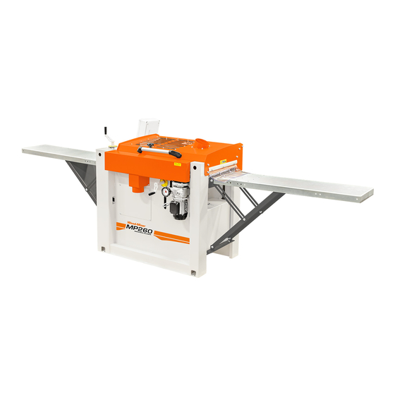
All other uses of the planer are forbidden. The MP260 is a planer/moulder that can work four sides of a workpiece in one action. The planer/ moulder is contained in a stable and strong chassis. The table is made of planed cast iron. - Page 6 The length required depends on the length of the workpieces you want to plane. The minimum length is 8 m. Higher risk area 3m(10 ft ) Control panel Outfeed 8m (26 ft) 6m (20ft) Infeed table MP260 table Operator’s position 3m(10 ft ) Safety distance for all other persons doc081920 INTRODUCTION...
- Page 7 INTRODUCTION Machine description ANCHORING It is recommended that the MP260 planer/moulder be anchored to the floor using 12 mm screws. LIST OF THE TOOLS REQUIRED TO WORK WITH THE PLANER/ MOULDER: Hex key 4 mm (supplied) Hex key 5 mm ...
-
Page 8: Chip Extractor
These spacer rings are necessary to set the required height. Chip Extractor MP260 planer/moulder must be connected to chip extractor with a capacity of at least 5 000m Remember that chip container has to be equipped with an air vent (e.g. a fine net or filter if dust are collected indoors). -
Page 9: Planer/Moulder Major Components
Kolo, Nagórna 114 St, Poland at +48-63-2626000. From the continental U.S., call our toll-free Parts hotline at 1-800-525-8100. Please have the machine identification number and your customer number ready when you call. Wood-Mizer will accept these methods of payment: Visa, Mastercard, or Discover ... -
Page 10: If You Need Service
INTRODUCTION If You Need Service If You Need Service From Europe call your local distributor or our European Headquarters and Manufacturing Facility in Kolo, Nagórna 114 St, Poland at +48-63-2626000. From the continental U.S., call us toll-free at 1-800-525-8100. Ask to speak with a Customer Service Representative. Please have your machine identification number and your customer number ready when you call. -
Page 11: Safety
Safety Safety Symbols SECTION 2 SAFETY Safety Symbols The following symbols and signal words call your attention to instructions concerning your personal safety. Be sure to observe and follow these instructions. DANGER! indicates an imminently hazardous situation which, if not avoided, will result in death or serious injury. - Page 12 IMPORTANT! It is always the owner's responsibility to comply with all applicable federal, state and local laws, rules and regulations regarding the ownership and operation of your Wood-Mizer planer/moulder. Wood-Mizer planer/moulder...
- Page 13 Safety Safety Instructions Keep the Machine And Area Around Clean DANGER! Maintain a clean and clear path for all necessary movement around the planer/moulder and lumber stacking areas. Failure to do so will result in serious injury. Dispose of Sawing By-Products Properly ...
- Page 14 Safety Planer/moulder operation DANGER! Always be aware of and take proper protective measures against rotating shafts, pulleys, fans, etc. Always stay a safe distance from rotating members and make sure that loose clothing or long hair does not engage rotating members resulting in possible injury. WARNING! Beware of rotating parts.
- Page 15 Safety Planer/moulder operation When planing smaller material, it should be stiffened/extended, e.g. with a longer piece of wood. Never stand in front of the material being fed or received, because it may suddenly kickback uncontrollably towards the operator. This applies to both the in and outfeed sides, although the risk is higher on the infeed side.
- Page 16 Always be sure that all safety decals are clean and readable. Replace all damaged safety decals to prevent personal injury or damage to the equipment. Contact your local distributor or Wood-Mizer Customer Service to order more decals. IMPORTANT! If replacing a component which has a safety decal affixed to it, make sure the new component also has the safety decal affixed in the same place.
- Page 17 Safety Safety Labels Description Safety Labels Description See table below for safety labels description. TABLE 2-0 Label View Label Number Description 096317 CAUTION! Carefully read operator’s manual before handling the machine. Observe instructions and safety rules when operating. 099220 Close guards prior to operating the machine 099220 099221...
- Page 18 Safety Safety Labels Description TABLE 2-0 096316 Electric box opening is possible with the switch in “0” position only. 096319 Always disconnect the power cord before opening the electric box. 524993 CAUTION! Hand injury hazard S12004G Always wear safety goggles when operating the planer/moulder! EGdoc081920 Safety...
- Page 19 Safety Safety Labels Description TABLE 2-0 S12005G Always wear protective ear muffs when operating the planer/moulder! 501465 Always wear safety boots when operating the planer/moulder! 512107-1 Always wear safety gloves when operating the planer/moulder! S20098 Motor rotate direction 087649 Warning stripes 502481 P85070 CE safety certification...
-
Page 20: Setup
Setup MP260 Moulder Assembly SECTION 3 SETUP MP260 Moulder Assembly Some of the machine components need to be assembled by the user before first usage. 1. Operator’s panel. Mount the operator’s panel (A) using three M8x20 socket head bolts (B), flat and spring washers. - Page 21 Setup MP260 Moulder Assembly 2. Infeed and outfeed table (optional equipment). Install the infeed table to the moulder using M8x16 screws with hex socket head and washers (A). Then install the supporting plate (B) using existing bolts (C). Tighten all fasteners by hand. Using the adjusting screws (D) adjust the table, so is level and on the same height as the moulder cast iron table (double check this with a long, straight tube or flat board).
-
Page 22: Planer/Moulder Setup
Setup Planer/moulder setup Planer/moulder setup IMPORTANT! Before starting to use the planer/moulder you have to meet the following conditions: Set up the planer/moulder on firm, level ground and level the planer/moulder. Secure the planer/moulder to the ground to prevent moving during operation. A cement pad with 12 mm diameter anchor bolts is recommended. - Page 23 Setup Planer/moulder setup See figure 3-3. E-STOP Operator’s position FIG. 3-3 MP260 Setup doc081920...
- Page 24 Setup Planer/moulder setup See table 3-1. Have a qualified electrician install the power supply (according to EN 60204 Standard). The power supply must meet the specifications given below. Model Voltage Total power Total amperage MP260EA12S 1X230V AC 11,1kW 67,1A MP260EA12S-V 1X230V AC 11,47kW 69,5A...
-
Page 25: Setup Of Upper And Lower Cutter Heads
Setup Setup of upper and lower cutter heads machine’s parts are tightened, especially working element covers. Be sure that no one than operator is in the high risk area. Turn on the chip extractor. DANGER! Connect planer/moulder electrical installation. - Page 26 Setup Setup of upper and lower cutter heads See Figure 3-1. Lower cutter Upper cutter TOP VIEW FIG. 3-1 UPPER/LOWER CUTTER DESIGN The cutter heads have the following specifications: Lower Cutter Upper Cutter Diameter: 2 13/16" (72mm) Diameter: 2 13/16" (72mm) Width: 11 13/16"...
- Page 27 Setup Leveling lower cutter straight planer knives See Figure 3-2. Knife height 10 mm open end adjusting screw wrench (supplied) Gib for NOTE: This item often goes by moulding knife many names - wedge, chip breaker, block, knife lock bar, clamp, or gib.
- Page 28 Setup Leveling lower cutter straight planer knives 1. Place the straight edge (the base of a carpenter’s square is shown) across the corner of the cast iron table bed as shown below. See Figure 3-3. Straight edge Feed table Knife edge FIG.
- Page 29 Setup Leveling lower cutter straight planer knives See Figure 3-4. 2. Adjust knife height 1. Loosen gib bolts FIG. 3-4 5. Insert the 10 mm wrench in the track between the gib and the cutter. 6. Loosen (do not remove) the gib lock bolts that hold the knife. 7.
- Page 30 Setup Initial setup of upper cutter Check that the knife is level in the cutter head by rotating the head to see if the knife blade barely comes in contact with and moves the straight edge very slightly. (See Figure 3-3.) Adjust one side until correct, and then adjust the other side in similar fashion.
- Page 31 Setup Initial setup of upper cutter See Figure 3-6. Lower Cutter Upper cutter TOP VIEW FIG. 3-6 The upper horizontal cutter should be parallel to the machine table. This is set from fac- tory, but the setting can become maladjusted by rough handling during transport or by the machine being subject to impact.
- Page 32 Setup Leveling the upper cutter straight planer knives Leveling the upper cutter straight planer knives The upper cutter knives are adjusted in a similar way to the lower cutter knives. However, there is an aluminum knife-setting block that is supplied with the machine for the purpose of setting the upper cutter knives.
- Page 33 Setup Replacing cutter straight planer knives CAUTION! If the height adjusting screws are screwed too tight, the knife will crack. 6. Repeat this procedure on all straight knives you have installed in the head. Replacing cutter straight planer knives This procedure is the same for upper and lower cutters. 1.
- Page 34 Setup Adjusting cutting depth of the lower cutter See Figure 3-8. The adjusting plates are held in place by countersunk screws. No plate currently loaded: wood takeoff would be 5/32” (4mm). (Hidden) FIG. 3-8 The 2mm spacer is the most common setting. NOTE: The spacer plates can be fitted in two ways.
- Page 35 Setup Adjusting upper cutter depth Adjusting upper cutter depth The cutting depth of the upper cutter is adjusted by turning the adjustment crank handle that raises and lowers the cast iron table in the planer. Each turn of the crank raises or lowers the machine table 5/32”...
- Page 36 Setup Moulding knives in upper and lower cutters Upper cutter head removes 1/8" Upper cutter head removes 3 mm Resulting thickness 7/8" Resulting thickness 21 mm Moulding knives in upper and lower cutters Moulding knives can be mounted both in the lower and the upper cutter. The moulding knives must always be mounted in pairs and in the same lateral position in the opposite slots of the cutter head.
-
Page 37: Side Cutter Setup
Setup Side cutter setup See Figure 3-10. MMP002 FIG. 3-10 Side cutter setup WARNING! Before adjusting the knives on this machine always turn off the electrical circuit supplying power to the machine. Failure to fol- low this may result in serious injury or death. WARNING! Wear gloves when working with knives in the machine. - Page 38 Setup Side cutter setup Gloves. SIDE CUTTER DESIGN The side cutters have the following specifications: Spindle Axle: Diameter 30 mm Cutting Height: Maximum 3 15/16" (100 mm) Rotation Speed: 7000 rpm Cutting Depth: Maximum 1 3/32" (28 mm) ...
- Page 39 Setup Side cutter setup See Figure 3-12. Locking nut Spacers Head Spacers (if needed) FIG. 3-12 REMOVING RIGHT OR LEFT SIDE CUTTER WARNING! Wear gloves when working with knives in the machine. Failure to follow this may result in serious injury or death. See Figure 3-13.
- Page 40 Setup Side cutter setup See Figure 3-14. Use the 30 mm and 12 mm open-end wrench in combination to loosen the nut on the top of the shaft. NOTE: The lock nut and the spindle of the movable side cutter have left-hand threads. FIG.
- Page 41 Setup Side cutter setup See Figure 3-15. Rotation direction Lock screw Dowel pins MMP003 FIG. 3-15 Ensure that the chip deflector in front of the movable cutter does not get bent by the unplaned edge of the work piece coming in contact with the cutter. Be cautious process- ing work pieces of various widths.
- Page 42 Setup Side cutter setup See Figure 3-16. 40 mm Spacer 20 mm Spacer 10 mm Spacer 5 mm Spacer Set of Spacers (0.1 - 2.0mm) FIG. 3-16 Side cutter shims are used to raise the cutter head up and down on the cutter shaft. Using shims allows the precise setting of the cutter head, and when locked in place, your setting will not change.
- Page 43 Setup Setting the movable side cutter head The top nut should then be replaced on the top of the shaft using two open-end wrenches – one to hold the shaft, and one to tighten the nut. (See figure 3-14.) Setting the movable side cutter head The movable side cutter head has a locking bolt under the table, on the output side.
- Page 44 Setup Setting the movable side cutter head This initial setting will only be an approximation; for now, we are mainly setting the second right side fence. Once this second right side fence is set, you will be able to accurately measure the desired width.
-
Page 45: Feed Rollers
FIG. 3-20 Feed rollers The MP260 has five feed rollers, which feed the work pieces through the machine. Four of these rollers are of ribbed metal and the last one has a rubber coating so that the sur- face of the work piece will not be marked when it exits the machine. -
Page 46: Leveling The Machine Cast Iron Table
Setup Adjusting the feeding speed IMPORTANT! Wood debris can accumulate under the feed roller spring mounted bearings. This impairs the feeding and increases the risk of the work piece being hurled out of the machine. Check these areas and, if necessary, remove the wood debris that has accumulated there. -
Page 47: Running The First Test Board
Setup Running the first test board 3. If possible, turn the machine table crank until the block comes very close to the cutter. If it is impossible to raise the table, you later have to take the measurement between the table and the cutter head instead of using the block. - Page 48 Setup Running the first test board See Figure 3-21. Power On Indicator Power On/Off Emergency Stop Feed Motor Lower cutter Fixed side cutter Movable side Upper cutter On Motors cutter On FIG. 3-21 1. Turn on the power. Power On Indicator should illuminate. 2.
- Page 49 Setup Running the first test board See Figure 3-22. Feed Speed Adjusting Knob FIG. 3-22 5. Place the board on the infeed side of the table against the fence. 6. Slide the board into the machine, with the right side firmly against the fence, until you feel the feed rollers begin to pull the board through the machine.
- Page 50 Setup Side cutter fence setup Side cutter fence setup The right side cutter has two fences: the first and second side cutter fence. They are both attached in similar fashion to the cast iron table. See Figure 3-23. Here are their locations in the machine: First side cutter fence Second side cutter fence FIG.
- Page 51 Setup Side cutter fence setup See Figure 3-24. Second side cutter fence Adjustment bolts FIG. 3-24 When your test boards are complete, and you are satisfied with your setup, you can begin running material through the machine. FEEDING THE MACHINE Ensure you have adequate room for the material that you will be putting in to and taking out of your planer.
-
Page 52: Operation
NOTE: None of the motors will start if the planer’s observation/protec- tive lid is not securely closed, or if the Emergency Stop Button is depressed. The MP260 is equipped with a lid switch that must be engaged before the machine can be started by the control panel buttons. doc081920... - Page 53 Check that all tools used in the setup of the machine are removed from the machine before starting any of the motors. The lid must be securely fastened down before the MP260 can be operated. Operation doc081920...
-
Page 54: Planing Tips
Operation Planing tips The Emergency Stop Button must be pulled out to allow motors to be started. NOTE: The best way to ensure that it is in the correct position is to depress the Emergency Stop Button in and then pull it out until you here a click. - Page 55 Operation Sizing stock against the fences. If you are going to produce a large amount of a moulding there is an additional lock- ing screw to secure cutter 3. The locking screw is recessed in a hole on the top of the carriage.
- Page 56 Planing narrow stock The MP260 can process very narrow stock. However, a motion-limiting block is posi- tioned in the machine between the two tubes that the left side vertical cutter head moves on. This limiting block is held in place by two bolts that are accessible underneath the block.
- Page 57 Operation Tongue and groove Tongue and groove When setting up this machine for tongue and groove material, start with several short pieces of stock similar in size (width and thickness) to your finished product. For tongue and groove that you have kept a sample from a previous run of this material, place the tongue and groove board from this previous run in the machine and match the knife height to match this original board.
-
Page 58: Maintenance
Maintenance Overview SECTION 5 MAINTENANCE DANGER! Remove power before clearing debris or any other mainte- nance activity. Failure to follow this will result in serious injury or death. Follow the OSHA lockout procedures given at the end of this section. Overview Your planer is a precision machine, and will provide you with professional results if kept in good condition. -
Page 59: After Each Use
Maintenance After each use The machine table should regularly be cleaned and treated with a lubricant, for example low-viscosity oil, silicon lubricants, or wax (3-1 oil, ChuteLube, silicon sprays, etc.). After each use 1. Clean the machine from wood debris. Also check the chip outlets and the hoses. Remove wood debris that has accumulated under the machine. - Page 60 Maintenance Lubrication points 1. The bearing holders and springs of the feed rollers. See Figure 5-1. Total of 10 - four steel rollers and one rubber FIG. 5-1 2. Lubricate the trapezoidal threaded bars. See Figure 5-2. Located at all four corners FIG.
- Page 61 Maintenance Lubrication points 3. Lubricate the chain and sprockets for height adjusting the table. Check the tension of the chain.) See Figure 5-3. View from bottom, looking up; outfeed side; cover panel removed. FIG. 5-3 The carriage of the movable cutter. See Figure 5-4.
- Page 62 Maintenance Cleaning the metal feed rollers The chain transmission of the feed rollers. See Figure 5-5. Cover removed. FIG. 5-5 Knives, spacers, pressure rollers and side rollers. See Figure 5-6. FIG. 5-6 Cleaning the metal feed rollers Pitch may build up on the metal feed rollers if you are planing wood that has high resin content.
- Page 63 Maintenance Table lift assist chain adjustments 1. Clean pitch buildup from the feed rollers with a soft wire brush (i.e. a brush with brass bristles) and some cleaning solvent to assist in loosening the pitch. CAUTION! Do not spray/pour cleaning fluid directly on to the feed roll- ers.
- Page 64 Maintenance Table lift assist chain adjustments See Figure 5-7. Outfeed view, chain adjustment sprocket lock nut - use 17mm wrench FIG. 5-7 See Figure 5-8. View from bottom, looking up; outfeed side; cover panel removed. FIG. 5-8 1. Remove the cover panel by using a 5 mm hex wrench. 2.
-
Page 65: Replacing Feed Chain Gear Sprocket Set Screw
Replacing feed chain gear sprocket set screw The feed roller sprockets in the MP260 are equipped with set screws that are designed to shear off their heads when the feed system is overloaded. For example, if the size of the material being fed into the machine is more than the machine can handle, the feed roller sprocket set screw will break off to protect the feed motor and drive train of the machine. -
Page 66: Removing And Replacing Feed Chains
Maintenance Removing and replacing feed chains lining up the set screw hole on the feed sprocket to the channel on the shaft. Removing and replacing feed chains Each chain has a master link, which must be disassembled in order to remove the chain. The master links come from the factory facing outward, and they are easily recognizable because they look different from the rest of the links. - Page 67 Replacing stationary vertical cutter belt Replacing stationary vertical cutter belt 1. Remove the collection hose and cover plate on the front of the MP260. 2. Loosen (do not remove) 4 cap head mounting screws holding the pulley of the stationary vertical cutter.
- Page 68 Maintenance Replacing stationary vertical cutter belt See Figure 5-12. Viewed from infeed side Belt tension adjustment bolt locking nut Belt tension adjustment bolt Motor mount FIG. 5-12 5. Back out the tension adjusting bolt until the front of the bolt is flush with the front of the belt tension bolt bracket, but do not remove the bolt from the bracket.
- Page 69 Maintenance Replacing movable vertical cutter belt 13. Replace the cover plate and collection hose. Replacing movable vertical cutter belt This process is very similar to removing and replacing the stationary vertical cutter belt, but with a few minor differences related to the exterior parts of the machine you need to remove to gain access to the belt.
- Page 70 Maintenance Replacing movable vertical cutter belt See Figure 5-14. Use a 6 mm hex wrench to loosen mounting screws one turn Mounting screws Cutter pulley Belt Motor pulley FIG. 5-14 4. Loosen (do not remove) 4 cap head mounting screws holding the pulley of the stationary vertical cutter.
- Page 71 Maintenance Replacing movable vertical cutter belt 6. Use a 13mm open-end wrench to loosen the locking nut that secures the tension adjust- ing bolt in place. 7. Back out the tension adjusting bolt until the front of the bolt is flush with the front of the belt tension bolt bracket, but do not remove the bolt from the bracket.
- Page 72 Maintenance Replacing top horizontal cutter belt Replacing top horizontal cutter belt 1. Loosen slightly mounting bolts (A). Move up and remove the belt cover (B). 2. Loosen the locking bolt (C). 3. Pull the motor with pulley up and remove the belt. 4.
- Page 73 Maintenance Replacing bottom horizontal cutter belt Replacing bottom horizontal cutter belt 1. Loosen and remove mounting bolts (A) with washers. Remove the belt cover (B). 2. Loosen the locking nut (C). 3. Pull the motor with pulley up and remove the belt. 4.
-
Page 74: 5.11 Sharpening Knives
Maintenance Sharpening Knives 5.11 Sharpening Knives The condition of your machine’s knives will affect the quality and precision of the cut. Pay close attention to the quality of the cut to get an idea about the condition of the machine’s knives. -
Page 75: 5.12 Long-Term Storage
Maintenance Long-term storage 5.12 Long-term storage If the machine is not used for a long period of time, do as follows: Disconnect the power cord. Perform all routine actions described above. Remove the knives with mounting strips or clamping wedges and store them well ... -
Page 76: Safety Devices Inspection (European Union Market Only)
Maintenance Safety Devices Inspection (European Union Market only) 5.13 Safety Devices Inspection (European Union Market only) MP260S Moulder – Safety Devices Inspection Safety devices on the machine which must be checked before every shift: E-STOP button and its circuit inspection, ... -
Page 77: Electrical Lockout Procedures (Us Market Only)
Maintenance Electrical lockout procedures (US Market only) Open the cutter housing cover; All motors should be stopped. Pressing any of “I” buttons should not start the motors. Close the cutter housing cover. Motors should remain stopped until they are restarted with any of “I” buttons. ... - Page 78 Maintenance Electrical lockout procedures (US Market only) Lockout procedures must be followed (see OSHA regulation 1910.147). Never rely on machine stop control for maintenance safety (emergency stops, on/off buttons, interlocks). Do not reach into moving blades or feed systems. Allow all coasting parts to come ...
- Page 79 Maintenance Electrical lockout procedures (US Market only) lockout in accordance with this procedure. All operators, upon observing a machine or piece of equipment which is locked out to perform servicing or maintenance shall not attempt to start, energize, or use that machine or equipment. SEQUENCE OF LOCKOUT 1.
- Page 80 Maintenance Electrical lockout procedures (US Market only) 1. Check the machine or equipment and the immediate area around the machine to ensure that nonessential items have been removed and that the machine or equipment compo- nents are operationally intact. 2. Check the work area to ensure that all personnel have been safely positioned or removed from the area.
-
Page 81: Troubleshooting
Troubleshooting Operation problems SECTION 6 TROUBLESHOOTING DANGER! Disconnect power before clearing debris or any other maintenance activity. Failure to follow this will result in serious injury or death. Follow the OSHA lockout procedures reprinted in the safety section. DANGER! Keep hands away from the knives. Failure to follow this will result in serious injury or death. - Page 82 Troubleshooting Operation problems Problem Possible Cause Remedy The entire surface is fuzzy. 1. The workpiece has high moisture 1. Dry the timber before machining it. content. 2. Grind the knives. It is especially 2. The knives have lost their important that the knives are sharp sharpness.
- Page 83 Troubleshooting Operation problems Problem Possible Cause Remedy The width of the machined 1. The workpiece moves away from 1. The right-side fences are set incor- board differs. the side fences. rectly. Adjust them according to the instructions. 2. The locking handle of the mov- able cutter has not been tightened.
-
Page 84: Mechanical Or Electrical Problems
Troubleshooting Mechanical or electrical problems Mechanical or electrical problems Problem Possible Cause Remedy None of the motors can be 1. The cover is not entirely closed. 1. Firmly tighten the locking knob on the started. 2. The emergency stop button is cover. - Page 85 Troubleshooting Mechanical or electrical problems Problem Possible Cause Remedy The workpiece is fed poorly or 1. The shear pin in the out-feed 1. Remove the planetary gear and not at all through the machine. roller is broken. replace the broken shear pin. 2.
- Page 86 Troubleshooting Mechanical or electrical problems Problem Possible Cause Remedy The workpiece is fed jerkily 1. The machine table is covered 1. 6. Clean and lubricate the table. through the machine. with resin or rust. 2. Replace the bent feed roller. 2.
- Page 87 Troubleshooting Mechanical or electrical problems Problem Possible Cause Remedy Vibration or rumble in the side 1. The moulding knives are incor- 1. Demount the cutter head, and clean cutter. rectly mounted. and mount the knives and the chip breakers correctly. Identical knives 2.
-
Page 88: Planer/Moulder Specifications
PLANER/MOULDER SPECIFICATIONS Overall dimensions SECTION 7 PLANER/MOULDER SPECIFICATIONS Overall dimensions See figure 7-1. The overall dimensions of the MP260 Planer/moulder are shown below (all dimensions in millimeters). FIG. 7-1 MP260 doc081920 PLANER/MOULDER SPECIFICATIONS... -
Page 89: Specifications Of The Planer/Moulder
PLANER/MOULDER SPECIFICATIONS Specifications of the planer/moulder See table 7-1. Weight of the MP260 planer/moulder are given in the table below. Planer/moulder type MP260 Weight 440 kg TABLE 7-1 Specifications of the planer/moulder See table 7-2. Wood-Mizer MP260 planer/moulder nomenclature is given in the table below. - Page 90 2,7kW 0,37kW Wood-Mizer Part # 533651-UL 533651-UL 533651-UL 533651-UL 532808-UL TABLE 7-3 See table 7-4. Feed rate Planer/moulder type MP260 with constant MP260 with adjustable feed speed feed speed Feed Speed 5 m/min 2-12 m/min TABLE 7-4 doc081920 PLANER/MOULDER SPECIFICATIONS...
- Page 91 PLANER/MOULDER SPECIFICATIONS Specifications of the planer/moulder See table 7-5. The noise level generated by Wood-Mizer planer/moulder is given in the table 1 2 3 below Noise Level Planer/Moulder MP260 = 82,2 dB (A) Equipped with electric motor = 100 dB (A)
- Page 92 PLANER/MOULDER SPECIFICATIONS Specifications of the planer/moulder See table 7-7. Other specifications of the planer/moulder are listed below Cutter Specifications Number of knife sockets Upper cutter diameter 88 mm Upper cutter width 410 mm Upper cutter max. planning depth 4 mm Upper cutter max.
-
Page 93: Dust/Chip Extractor Specifications
4 mm 21 mm 29 mm TABLE 7-8 According to EN 847-1:2005 European Standard Dust/Chip Extractor Specifications See Table 7-9. Specifications of the dust/chip extractors used on the MP260 are listed below. Airflow 4000 m Inlet diameter 3x100mm 1x125 mm... - Page 94 And is in conformity (parts of) with the following Harmonized Standards: EN12100:2012 EN12750:2013 Responsible for technical information Bo Mårtensson, CEO, Wood-Mizer AB Wood-Mizer AB Östersund 2019-01-09 Bo Mårtensson, CEO The basis for this translation is the English-language original declaration of conformity issued by Moretens. This is...
Need help?
Do you have a question about the MP260 and is the answer not in the manual?
Questions and answers