Advertisement
Quick Links
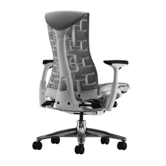
Embody
"Knocked Down" chair Assembly
™
©
2018 Herman Miller, Inc., Zeeland, Michigan Printed in U.S.A.
®
, Abak, Action Office, Avive, Co/Struc, Ethospace, Intersect, Meridian, Passage, Prospects, Quadrant, Resolve, Scooter, Vivo interiors, Lifework, Teneo,
and V-Wall are among the registered trademarks of Herman Miller Inc.
™
Burdick Group, CLT, Flex-Edge, My Studio Environments, and Q system, are among the trademarks of Herman Miller Inc.
Illustrations and specifications are based on the latest product information available at the time of publication. The right is reserved to make changes in design and specifications
at any time, without notice, and also to discontinue products.
1B4B13 REV E
1
Advertisement

Related Manuals for HermanMiller Embody Knocked Down


Summary of Contents for HermanMiller Embody Knocked Down
- Page 1 Embody “Knocked Down” chair Assembly ™ 1B4B13 REV E © 2018 Herman Miller, Inc., Zeeland, Michigan Printed in U.S.A. ® , Abak, Action Office, Avive, Co/Struc, Ethospace, Intersect, Meridian, Passage, Prospects, Quadrant, Resolve, Scooter, Vivo interiors, Lifework, Teneo, and V-Wall are among the registered trademarks of Herman Miller Inc. ™...
-
Page 2: Parts Included
Parts Included: NOTICE! Remove product from packaging and inspect all components for any damage which may have occurred during shipping, before proceeding with product assembly. (Base shown with adjustable arms) Chair Base Assembly Chair Back (2) M6 x 12 Left Right T-27 Torx Spine Cap Screw... -
Page 3: Installation Instructions
Installation Instructions: Remove Base Assembly, Chair Back, and Spine from packaging and place on a clean flat surface. Using the T-27 Hand Tool remove the Spine Cap Screws by turning in a counter-clockwise direction. NOTICE! Remove the Spine Caps and Shaft and set aside. Gently rotate Antler upwards until you can easily remove caps and shaft. - Page 4 Align the Spine to the Chair Back so that the head of the Spine is in-line with the Antler openings. Antler Spine Heel Detachable Cardboard filler Note: Placing the detachable cardboard filler under the heel of the Spine will aid in the next Rotate Antler up until you can align the head of couple of steps.
- Page 5 Slide Spine Shaft through the head of the Spine and into the Antler tail. The Shaft should stick out evenly on both ends Set the Left and Right Hand End Caps on their correspond- ing ends of the Spine Shaft. Inside View of Right-Hand Cap Inside View of...
- Page 6 Insert the (2) Spine Cap Screws and tighten in a clock-wise direction using the sup- plied T-27 Hand Tool. Tighten until snug and add 1 quater turn. (Torque specs = 35 in-lbs, 4 n-m) (shown actual size) Before attaching the back check to make sure the seat fabric flaps are placed securely over the seat clips on the back...
- Page 7 Remove Back Assembly from Clip worksurface and align the spine to the Post tilt, and seat locator post and clips to the to the back attachment points as shown in the figure on the right. Check to make sure the seat fabric flaps, as noted in Clip step 9, are secure over the seat clips and do not visbly protrude where the...
- Page 8 . Insert (2) Chair Back Screws into the Chair Back and tighten in a clock-wise direction using the supplied T-40 hand tool. Tighten until snug and add 2 and 1/2 turns. (Torque specs = 90 in-lbs, 10.2 n-m) (shown actual size) Insert (2) Spine Screws into the Spine Heel and into the Tilt.
- Page 9 Insert the Back Angle Knob into the Spine by sliding it into the slot as shown. Make sure the Knob is fully engaged by pushing it in as far as possible. Verify that the knob is securely seated by striking the end of the Knob with either the palm of your hand or a rubber mallet.
Need help?
Do you have a question about the Embody Knocked Down and is the answer not in the manual?
Questions and answers