
Related Manuals for EXFO OSA20


Summary of Contents for EXFO OSA20
- Page 1 Getting Started OSA20 Optical Spectrum Analyzer Optical Spectrum Analyzer www.EXFO.com...
-
Page 2: Table Of Contents
Connecting a Light Source to the OSA20 ......................18 Connecting a Mouse and Keyboard to the OSA20 .....................19 Turning on the OSA20 and Accessing the Home Window .................20 Turning off the OSA20 ............................21 For full details on how to use the OSA20, see CTP10 User Guide available on the USB key provided with the instrument. -
Page 3: Introducing The Osa20
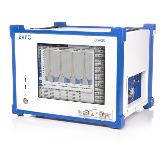
Introducing the OSA20 The OSA20 is a diffraction-grating based optical spectrum analyzer, using a touch sensitive display with multi-touch gesture control. It provides an extensive suite of built-in analysis functions enabling input signal measurement and analysis for many common applications. - Page 4 Except ±0.35 dB in -55 dBm and Burst sensitivities, except for water absorption lines, over 18–28°C all sensitivity settings. Sweep cycle /100 nm at -60 dBm sensitivity at center wavelength of 1475 nm. The validity of specifications depends on operating conditions (see OSA20 User Guide, Recalibrating the OSA20 on page 146).
- Page 5 Introducing the OSA20 Technical Specifications Interfaces and Electrical Optical interfaces Optical input SMF-28 type fiber User calibration output Built-in ELED (safety class 1) + Acetylene cell (user calibration by patch cord) Connector (input and FC/APC or FC/PC or SC/APC or SC/PC...
-
Page 6: Product Overview
Connector’s plate Optical connectors On/Off button label identifies the On/Off button that enables you to turn on or off the OSA20 (see Turning on the OSA20 and Accessing the Home Window on page 20). Multi-touch Screen The multi-touch screen enables you to perform all possible operations on the OSA20. - Page 7 USB 2.0 type-A ports located on the front panel. They enable you to connect USB devices such as: Keyboard and mouse if needed (see OSA20 User Guide, Connecting a Mouse and Keyboard to the OSA20 on page 19) USB key or hard disk to export your measurement results ...
- Page 8 Introducing the OSA20 Product Overview Left-side Panel: Cooling Fan The cooling fan, located on the left-side panel of the OSA20, extracts warm air from inside. A cover grid protects it. Cooling Fan Right-side Panel: Connectors The right-side panel of the OSA20 contains: A complete set of communication ports and interfaces for remote control and export of ...
- Page 9 OSA20 User Guide, Triggering the Optical Spectrum Acquisition on page 50. In RLT mode, this port is used as a gate: in OSA20 User Guide, see paragraphs RLT – Recirculating Loop Transmission on page 37 and Gate Acquisition (RLT mode only) on page 45.
- Page 10 For more information, see OSA20 User Guide, Using the OSA20 in Remote Control on page 137. MPORTANT The Ethernet ports can only be used for remote control of the OSA20. Any other use is not possible. Audio and Serial Ports Unused ports.
- Page 11 This port (also known as GPIB port) enables you to perform remote control operations. For more information, see OSA20 User Guide, Using the OSA20 in Remote Control on page 137. The IEEE 488 port is SELV classified; you must only connect it to interfaces of the same type.
-
Page 12: Safety Information
If the equipment is used in a manner not specified by the manufacturer, the protection provided by the equipment may be impaired. ARNING Use only accessories designed for your unit and approved by EXFO. For a complete list of accessories available for your unit, refer to its technical specifications or contact EXFO. -
Page 13: Other Safety Symbols On Your Unit
Direct current Alternating current The unit is equipped with an earth (ground) terminal. The unit is equipped with a protective conductor terminal. The unit is equipped with a frame or chassis terminal. On (Power) Off (Power) On/off (Power) Fuse OSA20... -
Page 14: Laser Safety Information
Do not replace any components while the power cable is connected. Unless otherwise specified, all interfaces are intended for connection to Safety Extra Low Voltage (SELV) circuits only. Capacitors inside the unit may be charged even if the unit has been disconnected from its electrical supply. OSA20... - Page 15 Safety Information Electrical Safety Information ARNING Use only the listed and certified AC/DC power adapter provided by EXFO with your unit. It provides reinforced insulation between primary and secondary, and is suitably rated for the country where the unit is sold.
-
Page 16: Getting Started With Your Osa20
The procedure to install the OSA20 into a 19-inch rack is available in the manual delivered with the rack mount kit. The OSA20 is designed for indoor use only, and is not dedicated to wet locations. It must be operated under proper environment conditions, as explained in the following procedure. - Page 17 8b. Slightly splay the lateral edges of the protective cover to unfasten the two side tabs from the back of the front frame. 8c. Gently pull horizontally the protective cover out of the front panel. 9. To tilt the OSA20 upward, deploy the two retractable legs located below it. OSA20...
-
Page 18: Connecting The Osa20 To A Power Source
Connecting the OSA20 to the Wall Socket Using the Power Adapter The OSA20 has a chassis connected to ground via the power supply cord. A protective ground connection by way of the grounding conductor in the power cord is essential for safe operation. - Page 19 Connecting the OSA20 to a Power Source Connecting the OSA20 to a 48 V DC Power Source You can directly connect the OSA20 to a 48 V DC power source by following the instructions given in this section. The following figure describes the 48 V connector located on the rear panel:...
-
Page 20: Connecting A Light Source To The Osa20
MPORTANT Keep protective caps on optical connectors when not in use. 2. Connect the light source to the optical input of the OSA20 with the appropriate jumper corresponding to the connector type mounted on your product, as indicated on the connector’s plate (see Front Panel on page 4). -
Page 21: Connecting A Mouse And Keyboard To The Osa20
Connecting a Mouse and Keyboard to the OSA20 To operate the OSA20, you can connect a USB mouse and keyboard to the USB-A 2.0 and USB-A 3.0 ports located on the front and right-side panels of the OSA20 (see Product Overview on page 4). -
Page 22: Turning On The Osa20 And Accessing The Home Window
After a few seconds, the button lights up. The startup procedure takes approximately 1 minute and 30 seconds. Once started, the OSA20 home window appears. For more details, see OSA20 User Guide available on the USB key provided with the OSA20. Analysis mode selection area... -
Page 23: Turning Off The Osa20
Turning off the OSA20 The following procedure explains how to correctly turn the OSA20 off. AUTION Never turn the OSA20 off by directly setting the power switch to O. To turn the OSA20 off: 1. Do one of the following:... - Page 24 Document version: 2.0.2.1 www.EXFO.com · info@exfo.com CORPORATE HEADQUARTERS 400 Godin Avenue Quebec (Quebec) G1M 2K2 CANADA Tel.: 1 418 683-0211 · Fax: 1 418 683-2170 TOLL-FREE (USA and Canada) 1 800 663-3936 © 2021 EXFO Inc. All rights reserved. ...
Need help?
Do you have a question about the OSA20 and is the answer not in the manual?
Questions and answers