Sign In
Upload
Manuals
Brands
EXFO Manuals
Measuring Instruments
OSA20
EXFO OSA20 Manuals
Manuals and User Guides for EXFO OSA20. We have
3
EXFO OSA20 manuals available for free PDF download: User Manual, Getting Started
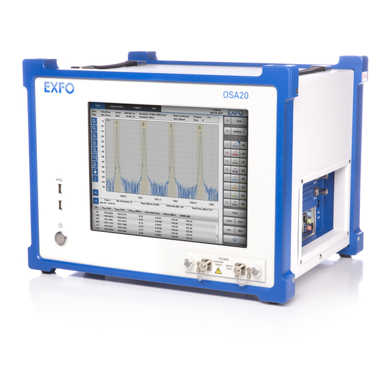
EXFO OSA20 User Manual (148 pages)
Optical spectrum analyzer
Brand:
EXFO
| Category:
Measuring Instruments
| Size: 3 MB
Table of Contents
Table of Contents
5
About this Manual
3
Important Safety Information for Your Product
9
1 Product Presentation
13
Technical Specifications
13
Product Overview
16
Figure 1: Front Panel
16
Front Panel
16
Figure 2: Left-Side Panel - Cooling Fan
18
Left-Side Panel: Cooling Fan
18
Figure 3: Right-Side Panel - Connectors
19
Right-Side Panel: Connectors
19
Figure 4: Rear Panel
21
Rear Panel
21
2 Installing and Connecting the OSA20
23
Unpacking and Installing the OSA20
23
Figure 5: Air Flow
24
Figure 6: Retractable Legs
24
Connecting the OSA20 to a Power Source
25
Connecting the OSA20 to the Wall Socket Using the Power Adapter
25
Connecting the OSA20 to a 48 V DC Power Source
26
Figure 7: Rear Panel - 48 V Connector
26
Connecting a Light Source to the OSA20
27
Handling USB Devices with the OSA20
28
Connecting USB Devices to the OSA20
28
Disconnecting USB Storage Devices from the OSA20
28
Sharing the OSA20 Display with an External Screen
29
3 Turning On/Off the OSA20 and Accessing an Analysis Mode
31
Accessing the OSA20 Home Window
31
Figure 8: OSA20 - Home Window
31
Setting General Parameters
32
Figure 9: OSA20 Settings
33
Accessing an Analysis Mode
35
Figure 10: RLT Mode - Typical Use
36
Figure 11: Analysis Mode Window
37
Turning off the OSA20
39
4 Defining Scan Measurement Parameters
41
Scanning the Optical Spectrum
41
Defining Scan Parameters
41
Figure 12: Scan Commands
41
Manually Starting/Stopping the Optical Spectrum Acquisition
45
Triggering the Optical Spectrum Acquisition
46
Generating Output Trigger Signals
47
Operating Scan Traces
48
Figure 13: Trace Commands
48
Setting Trace Types
49
Copying/Pasting Trace Data
50
Displaying/Hiding/Activating Traces
50
Figure 14: Trace Saving
51
Saving/Loading Traces
51
Handling Traces Files
53
5 Adjusting the Graph Display
55
Adjusting the Scale of the Graph with Zoom Commands
55
Performing Manual Measurements with Markers
57
Figure 15: Marker Positioning
57
6 Analyzing Traces
59
Figure 16: Analysis Menu
60
Figure 17: Analysis Results - Example Window (BBS Analysis Mode)
62
Figure 18: Analysis Results - Example Window (WDM Analysis Mode)
63
Defining PT Search Analysis Parameters
64
Figure 19: WDM Analysis Mode - PT Search
64
Setting up Peaks and Troughs Search
64
Figure 20: PT Search
65
Analyzing PT Search Results
66
Selecting the Component under Test (PCT Mode)
67
Defining Channel Detection Analysis Parameters
68
Setting up Channel Detection
68
Figure 21: WDM Display Mode: Grid
69
Figure 22: WDM Display Mode: Per Channel
70
Analyzing WDM Channel Detection Results
71
Defining Spectral Width Analysis Parameters
73
Figure 23: Threshold Algorithm
73
Setting up Spectral Width Analysis
73
Figure 24: Envelop Algorithm
74
Figure 25: RMS Algorithm
74
Figure 26: Gaussian Algorithm
75
Analyzing Spectral Width Results
76
Defining Xxdb Width Analysis Parameters
77
Figure 27: Threshold Algorithm (BBS Analysis Mode)
77
Setting up Xxdb Width Analysis
77
Figure 28: RMS Algorithm (BBS Analysis Mode)
78
Figure 29: Gaussian Algorithm (BBS Analysis Mode)
78
Analyzing Xxdb Width Results
79
Defining Λmean Analysis Parameters
80
Setting up Λmean Analysis
80
Analyzing Λmean Results
81
Analyzing Λpeak Results
81
Analyzing Λcenter and Σ Results
82
Analyzing FWHM Results
83
Analyzing Side Modes Spacing Analysis
84
Defining Notch Width Analysis Parameters
85
Setting up Notch Width Analysis
85
Figure 30: Notch Width - Notch Selection
86
Figure 31: Notch Width - Width Reference
86
Analyzing Notch Width Results
87
Defining Level Check Analysis Parameters
88
Setting up Level Check Analysis
88
Analyzing Level Check Results
89
Defining SMSR Analysis Parameters
90
Figure 32: SMSR Analysis
90
Setting up SMSR Analysis
90
Analyzing SMSR Results
91
Defining OSNR Analysis Parameters
93
Figure 33: OSNR Analysis
93
Setting up OSNR Analysis
93
Figure 34: OSNR Analysis - On-Off Method
94
Figure 35: OSNR Parameters
95
Analyzing OSNR Results
97
Defining Ripple Analysis Parameters
99
Setting up Ripple Analysis
99
Analyzing Ripple Results
100
Figure 36: Ripple Results
100
Defining Optical Power Analysis Parameters
101
Setting up Optical Power Analysis
101
Analyzing Optical Power / Gain / Loss Results
102
Analyzing Loss Measurement Results
103
Defining Loss Measurement Analysis Parameters
103
Setting up Loss Measurement Analysis
103
Analyzing Peak Power Density Results
104
Defining Peak Power Density Analysis Parameters
104
Setting up Peak Power Density Analysis
104
Defining Gain & NF Analysis Parameters
105
Setting up Gain and Noise Figure Analysis
105
Analyzing Gain and NF Results
107
Figure 37: Gain & NF Results
107
Defining Pass Band Test Analysis Parameters
109
Figure 38: Pass Band Test - in Reference Selection
109
Setting up Pass Band Test Analysis
109
Figure 39: Pass Band Test - out Reference Selection
110
Figure 40: Pass Band Test - Averaging Range: Fixed Range
110
Figure 41: Pass Band Test - Averaging Range: % Bandwidth 1
111
Figure 42: Pass Band Test - Averaging Range: PT Detection
111
Figure 43: Roll off Calculation - Transition in Band
112
Figure 44: Roll off Calculation - Transition out Band
112
Analyzing Pass Band Test Results
113
Defining Stop Band Test Analysis Parameters
114
Figure 45: Stop Band Test - in Reference Selection
114
Setting up Stop Band Test Analysis
114
Figure 46: Stop Band Test - out Reference Selection
115
Figure 47: Stop Band Test - Averaging Range: Fixed Range
115
Figure 48: Stop Band Test - Averaging Range: % Bandwidth 1
116
Figure 49: Stop Band Test - Averaging Range: PT Detection
116
Figure 50: Roll off Calculation - Transition in Band
117
Figure 51: Roll off Calculation - Transition out Band
117
Analyzing Stop Band Test Results
118
Defining Mask Test Analysis Parameters
119
Figure 52: PCT Analysis - Example of Mask Traces
119
Setting up Mask Test Analysis
119
Analyzing Mask Test Results
120
Figure 53: MSK HI Menu
120
7 Saving/Loading Configuration Settings and Handling Files
121
Saving Analysis Settings and Results
121
Loading Measurement and Analysis Settings
122
Handling Files Saved
123
8 Using the OSA20 in Remote Control
125
Preparing the OSA20 for Remote Control
125
Modifying the GPIB Address
125
Setting the Ethernet Ports
125
Figure 54: OSA20 Remote Parameters
126
Installing the USB Driver on the Remote Computer
128
Entering the Remote Mode
129
Switching Back to Local Mode
129
9 Performing Basic Maintenance Operations
131
Updating the OSA20 Firmware Version
131
Cleaning the OSA20
132
Cleaning the Cover of the OSA20
132
Cleaning the Fan Grid
132
Cleaning the Multi-Touch Screen
133
Replacing the External Power Fuse
133
Cleaning Optical Connectors
134
Figure 55: Optical Connectors (FC Type) - Cleaning
134
Calibrating the OSA20
136
Asking for a Factory Recalibration
136
Performing a User Calibration
136
Carrying the OSA20
137
Packaging for Shipment
137
10 Troubleshooting
139
Handling Errors and Warnings
139
Dealing with System Error Messages
139
Dealing with File Handling Error Messages
141
Dealing with User Calibration Error Messages
141
Dealing with Trace Analysis Warning Messages
143
Forcing the OSA20 to Shutdown & Restart
143
Using Remote Assistance Tools
144
Performing a Self-Test
144
Sending Debug Data to EXFO Support Service
144
Certification and Compliance
145
Table of Figures
147
Advertisement
EXFO OSA20 User Manual (166 pages)
Optical Spectrum Analyzer
Brand:
EXFO
| Category:
Measuring Instruments
| Size: 3 MB
Table of Contents
Copyright
2
Table of Contents
3
Regulatory Information
6
Introducing the OSA20
9
Technical Specifications
9
Product Overview
12
Conventions
19
Safety Information
21
Other Safety Symbols on Your Unit
22
Laser Safety Information
23
Electrical Safety Information
24
Getting Started with Your OSA20
27
Unpacking and Installing the OSA20
27
Connecting the OSA20 to a Power Source
29
Connecting a Light Source to the OSA20
31
Connecting a Mouse and Keyboard to the OSA20
32
Sharing the OSA20 Display with an External Screen
33
Turning on the OSA20 and Accessing the Home Window
34
Turning off the OSA20
35
Updating the OSA20 System Version
36
Updating the Operating System Version (Security Updates)
38
Setting up Your OSA20
39
Setting the Screen Brightness
39
Setting Spectral and Power Units
39
Setting the Date and Time
39
Accessing an Analysis Mode
41
Performing Measurement Scans
45
Defining the Scan Parameters
45
Zeroing the Dark Current
51
Manually Starting/Stopping the Optical Spectrum Acquisition
53
Triggering the Optical Spectrum Acquisition
54
Generating Output Trigger Signals
55
Configuring and Displaying Scan Traces
57
Operating Scan Traces
57
Handling Traces Files
63
Adjusting the Graph Display
64
Analyzing Traces
69
Setting up Peaks and Troughs Search
74
Selecting the Component under Test (PCT Mode)
77
Setting up Channel Detection
78
Setting up Spectral Width Analysis
84
Setting up Xxdb Width Analysis
89
Setting up Mean Wavelength/Frequency Analysis
92
Analyzing Central Wavelength and Sigma Value Results
94
Analyzing FWHM Results
95
Analyzing Side Modes Spacing Results
96
Setting up Notch Width Analysis
97
Setting up Level Check Analysis
100
Setting up SMSR Analysis
102
Setting up OSNR Analysis
105
Setting up Ripple Analysis
111
Setting up Optical Power Analysis
113
Setting up Loss Measurement Analysis
115
Setting up Peak Power Density Analysis
116
Setting up Gain and Noise Figure Analysis
117
Setting up Pass Band Test Analysis
121
Setting up Stop Band Test Analysis
127
Setting up Mask Test Analysis
133
Handling Files and User Data
135
Connecting/Disconnecting USB Storage Devices
135
Saving Analysis Settings and Results
135
Loading Measurement and Analysis Settings
137
Handling Files Saved
138
Deleting All User Data from the OSA20 Internal Drive
138
Restoring Factory Settings
139
Using the OSA20 in Remote Control
141
Preparing the OSA20 for Remote Control
141
Entering/Exiting the Remote Mode
144
Performing Basic Maintenance Operations
145
Cleaning the OSA20
145
Cleaning Optical Connectors
147
Performing a User Calibration
148
Replacing the External Power Fuse
149
Recalibrating the OSA20
150
Carrying the OSA20
150
Recycling and Disposal
150
11 Troubleshooting
151
Handling Errors and Warnings
151
Forcing the OSA20 to Shutdown & Restart
155
Using Remote Assistance Tools
156
Displaying the User Documentation
157
Contacting the Technical Support Group
158
Transportation
158
12 Warranty
161
General Information
161
Gray Market and Gray Market Products
161
Liability
162
Exclusions
162
Certification
162
Service and Repairs
163
EXFO Service Centers Worldwide
164
EXFO OSA20 Getting Started (24 pages)
Optical Spectrum Analyzer
Brand:
EXFO
| Category:
Measuring Instruments
| Size: 1 MB
Table of Contents
Table of Contents
2
1 Introducing the OSA20
3
Technical Specifications
3
Product Overview
6
2 Safety Information
12
Other Safety Symbols on Your Unit
13
Laser Safety Information
14
Electrical Safety Information
14
3 Getting Started with Your OSA20
16
Unpacking and Installing the OSA20
16
Connecting the OSA20 to a Power Source
18
Connecting a Light Source to the OSA20
20
Connecting a Mouse and Keyboard to the OSA20
21
Turning on the OSA20 and Accessing the Home Window
22
Turning off the OSA20
23
Advertisement
Advertisement
Related Products
EXFO Optical Xplorer OX1
EXFO OX1-M
EXFO OX1 PRO-M
EXFO OX1-I
EXFO OX1 PRO-I
EXFO OX1 Pro
EXFO OpticalRF
EXFO OSICS
EXFO OTH-7000
EXFO OTAU-9150
EXFO Categories
Test Equipment
Measuring Instruments
Laboratory Equipment
Control Unit
Analytical Instruments
More EXFO Manuals
Login
Sign In
OR
Sign in with Facebook
Sign in with Google
Upload manual
Upload from disk
Upload from URL