
Related Manuals for Freescale Semiconductor TWR-K64F120M


Summary of Contents for Freescale Semiconductor TWR-K64F120M
- Page 1 TWR-K64F120M Quick Start Guide Low-power MCUs at 120 MHz with FPU, up to 1 MB Flash and up to 256 KB SRAM Tower System Development Board Platform...
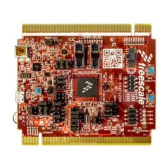
- Page 2 Get to Know the K64F120M Board General-Purpose TWRPI Plug-In Accelerometer Power/OpenSDA Mini-USB K64 JTAG OpenSDA Debug 1588 RESET K64 Micro-USB Potentiometer LEDs Board power Regulator 50 MHz OSC VBAT indicator Option Selector Enable/Disable Options Figure 1: Front side of TWR-K64F120M...
- Page 3 Potentiometer TWR-K64F120M Freescale Tower System Development Board Platform The TWR-K64F120M board is designed to work either in standalone mode or as part of the Freescale Tower System, a modular development board platform that enables rapid prototyping and tool re-use through reconfigurable hardware.
- Page 4 • MK64FN1M0VMD12 (120 MHz, 1 In this Quick Start Guide, you will learn MB Flash, 256 KB RAM, FPU, USB, how to set up the TWR-K64F120M board encryption, low power, 144 MAPBGA) and run the included demonstrated software. For more detailed information, • Dual-role USB interface with Micro-AB...
- Page 5 USB cable to the PC and the and MQX RTOS by clicking the relevant other end to the Power/OpenSDA micro-B links at freescale.com/CodeWarrior and connector on the TWR-K64F120M module. freescale.com/MQX. Allow the PC to automatically configure the USB drivers if needed.
-
Page 6: Setting Description
Quick Start Guide TWR-K64F120M Jumper Options The following is a list of all jumper options on the TWR-K64F120M. The default installed jumper settings are indicated in the shaded boxes. Jumper Option Setting Description 1–2 Enable V_BRD power supply to 50 MHz OSC... - Page 7 freescale.com Jumper Option Setting Description VBUS Signal on micro USB connector J17 connects to K64_VREGIN 1–2 to allow standalone USB operation K64 VREG IN Selector VBUS signal from TWR ELEV connector connects to K64_VREGIN to 2–3 allow USB operation with complete Tower System Output of USB power switch controlled by the VTRG_EN signal from 1–2 the K20 MCU.
-
Page 8: Option Setting
Quick Start Guide TWR-K64F120M Jumper Options (cont.) Jumper Option Setting Description Connect PTA8 to INT2 pin of accelerometer Accelerometer Connect PTA6 to INT1 pin of accelerometer IRQ Connection Disconnect PTA6 and/or PTA8 from INT1 and/or INT2 of accelerometer External External 10 K ohm Pulldown on SDHC_D3... - Page 9 freescale.com Jumper Option Setting Description Connect onboard 1.8 V or 3.3 V supply (V_BRD) to TWRPI 3 V General- power (GPT_VBRD) Purpose TWRPI V_BRD Power Disconnect from board 1.8 V or 3.3 V supply (V_BRD) to TWRPI Enable 3 V power (GPT_VBRD) GPIO 1–2 Connect PTB7 to RESET_OUT_B signal...
- Page 10 Quick Start Guide...
- Page 11 freescale.com...
-
Page 12: Get Started
Freescale, the Freescale logo, CodeWarrior and Kinetis are trademarks of Freescale semiconductor, Inc., Reg. U.S. Pat. & Tm. Off. Tower is a trademark of Freescale Semiconductor, Inc. All other product or service names are the property of their respective owners. © 2014 Freescale Semiconductor, Inc.
Need help?
Do you have a question about the TWR-K64F120M and is the answer not in the manual?
Questions and answers