
Subscribe to Our Youtube Channel
Related Manuals for Freescale Semiconductor TWR-MPC8309


Summary of Contents for Freescale Semiconductor TWR-MPC8309
- Page 1 Quick Start Guide TWR-MPC8309 PowerQUICC Processor with Industrial Connectivity and Protocol Off-Load Engine TOWER SYSTEM T-P23345-TWR-MPC8309-o1v6.indd 1 11/4/11 5:19 P...
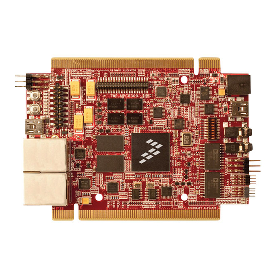
- Page 2 Ethernet Ports TWR-MPC8309 Freescale Tower System The TWR-MPC8309 module is part of the Freescale Tower System portfolio, a modular development platform that enables rapid prototyping and tool re-use through reconfigurable hardware. Elevate your design to the next level with this industrial power house by building your Tower System today.
- Page 3 TWR-MPC8309 The TWR-MPC8309 processor module can be operated as a stand-alone single board computer (SBC), a primary elevator connected system- on-module (SoM) or a Tower System rapid prototyping development platform. Freescale’s MQX™ software support enables applications to quickly migrate from Freescale microcontrollers up to the high-...
- Page 4 Quick Start Guide Step-by-Step Installation Instructions In this quick start guide, you will learn how to set up the TWR-MPC8309 module and run the included demonstration software. For more detailed information, please see the user manual found on the included DVD or at freescale.com/TWR-MPC8309.
- Page 5 Diagnostic routines have been included to verify the functionality of the board and can be run using the “diag” command in U-Boot. See the user manual for details. T-P23345-TWR-MPC8309-o1v6.indd 5 11/4/11 5:19 P...
-
Page 6: Connecting Cables
Connect the desired debugger hardware point-to-point networking demos on to the standard JTAG/COP header lining a single TWR-MPC8309 module. Any up pin 1 with the OBSEL configure Ethernet cable can be connected between switch setting in the OFF position. TWR-... -
Page 7: Configuration Switch Settings
1) Switch positions as printed on the switch 2) Schematic signal settings readable from software from MSB (top-left as bit 0) to LSB (bottom-right as bit 7) 3) Switch settings as printed on the switch, factory settings highlighted red T-P23345-TWR-MPC8309-o1v6.indd 7 11/4/11 5:19 P... -
Page 8: Warranty
Quick Start Guide Visit freescale.com/TWR-MPC8309 for the latest information on the TWR-MPC8309 module, including: • Board database: schematics, layout and BOM • User manual • Quick start guide • Software BSPs, industrial protocol evaluation stacks and CodeWarrior • Demos and tutorial • Fact sheet Support Visit freescale.com/support for a list of phone numbers within your region.
Need help?
Do you have a question about the TWR-MPC8309 and is the answer not in the manual?
Questions and answers