Advertisement
Quick Links
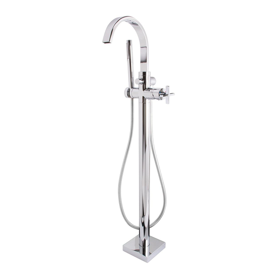
INSTRUCTIONS FOR MODELS
SB-2534
SB-2536
For additional assistance or service please contact:
SPEAKMAN
®
800-537-2107
customerservice@speakman.com
www.speakman.com
92-SB-2534-36-01
SPOUT ORIENTATION
2
• Orient the Base with the cold supply side in the
direction shown.
• If possible, dry fit the Faucet to the Base using
the Screws and Washers. Orient the Spout to the
inside of the bath tub.
• If your Faucet is not available at this time, make
sure the Base is positioned so the Faucet will
properly run water into the bath tub.
• Mark the mounting hole locations on the
wooden support.
• Mark the orientation of the Base on the wooden
support for reference.
NOTE: The Base has embossed letters "C" and
"H" to indicate cold and hot supply sides,
respectively. Ensure that the Base is oriented with
"C" being towards the "TUB" side and "H" being
towards the "WALL" side.
NOTE: Verify correct Spout orientation before securing the Base to the wooden support.
SUPPLY CONNECTIONS
4
• Apply sealant tape on the ½" NPT hot and cold
supply pipes and thread into the Base.
• Turn ON the water supply and check for leaks.
• Turn OFF the water supply.
• Secure the Protective Cover onto the Base with
the Screws provided.
The Base has embossed letters "C" and "H" to indicate cold and hot supply sides, respectively.
NOTE:
TOOLS AND SUPPLIES
Pencil
Phillips
Thread Seal
Screwdriver
Tape
Drill
Drill Bit
5/16"
6mm
Hex
2.5mm Hex
Key Wrench
Key Wrench
(Included)
(Included)
Level
Adjustable
Pipe
Wrench
Wrench
HELPFUL TOOLS & SUPPLIES:
Measuring
Safety
Tape
Glasses
TOP VIEW
COLD
HOT
PENCIL
WALL
BATH
TUB
SCREW
GUARD
HOT SUPPLY
BASE
COLD SUPPLY
IMPORTANT
SAFETY TIPS
• Be sure to read instructions thoroughly before
beginning installation.
• Cover the installation area(s) as deemed
necessary to prevent any loss of parts.
MAINTENANCE
Your new Speakman Product is designed for years of
trouble-free performance. Keep it looking new by
cleaning it periodically with a soft cloth. The use of harsh
chemicals and abrasives on any of the Speakman custom
finish products may damage the finish and void the
product warranty. Please be sure to only use approved
cleaners. Please contact Speakman for any clarification
of acceptable cleaners.
WARRANTY
Warranty information can be found at:
www.speakman.com
SITE PREPARATION
1
IMPORTANT! Lumber required for Wood Support shall be at least 2 x 6 dimensional lumber.
• Plan out the bath filler placement based on the dimensions in the "ROUGH-IN DIAGRAM".
• Cut a hole in the subfloor large enough to install the wood support between two floor joists.
• Secure a wood support 1-5/8" (41mm) - 4-5/8" (118mm) below the height of the finished floor.
NOTE: Concrete can be used as the floor support.
FINISHED
SUBFLOOR
FLOOR
CAVITY
1-5/8"
(41mm) MIN
4-5/8"
(118mm) MAX
WOOD SUPPORT
FLOOR JOIST
NOTICE: Adequate floor support is required. The wood support must be a minimum of 1.5" ( 38mm) thick
by 5.5" (140mm) wide. 2x6 lumber is adequate for this application.
BASE INSTALLATION
3
• If attached, remove the Faucet from the Base.
• Drill holes through the wood support with a
5/16" drill bit (not provided) using the marked
locations as the center point.
• If using concrete as the floor support, use
appropriate mounting hardware (not provided).
• Realign the Base to the position as marked.
• Secure the Base to the support with the Screws,
Nuts, Split-Washers and Washers provided.
• Verify the Base is level and tighten the
Screws/Nuts.
5/16"
NOTE: Floor structure shown is for REFERENCE ONLY.
Ensure your installation is properly oriented to the Bath Tub.
FINISHED FLOOR INSTALLATION
5
• Finish the floor leaving a 4-5/8" (117mm) by 4-5/8" (117mm) square hole for the Protective Cover.
• Cut the Protective Cover so it is flush with the finished flooring.
FINISHED FLOOR
PROTECTIVE
COVER
IMPORTANT
• Do not over-tighten any connections or damage
may occur.
• Shut off the water supply before beginning
installation.
• This installation manual covers several models.
While your models may look different, it will install
in the same manner.
• This Faucet has an operating range of 20-80 psi.
• CAUTION: Risk of personal injury. Do not use
the bath filler as a grab bar or support bar when
entering or exiting the bath. The bath filler is not
designed to support weight.
• Observe all local plumbing and building codes.
• Use appropriate drill bits for wood and other
materials.
• Installer supplied copper tubing (if used) must be
5/8" OD (1/2" Nominal).
BASE
CENTERLINE
2-1/2"
(64mm)
MIN
BATH
TUB
FINISHED
FLOOR
FLOOR
JOIST
WOOD
SUPPORT
6mm
WASHER
SPLIT-WASHER
NUT
FIT THE FINISHED FLOOR
BETWEEN THE
MIN AND MAX LINES.
4-5/8"
[117mm]
4-5/8"
[117mm]
6"
(152mm)
MIN
FINISHED
WALL
SCREW
BASE
5/16"
MOUNTING
HOLE
Advertisement

Related Manuals for Speakman SB-2534


Summary of Contents for Speakman SB-2534
- Page 1 • This Faucet has an operating range of 20-80 psi. MAINTENANCE • CAUTION: Risk of personal injury. Do not use Your new Speakman Product is designed for years of the bath filler as a grab bar or support bar when Drill Drill Bit trouble-free performance.
- Page 2 • Install the Hand Shower to the Hose, hand tighten, and place into the Hand Shower Holder. DIVERTER BUTTON HANDLE HAND SHOWER HOSE HOLDER HOSE SPEAKMAN SB-2534 / SB-2536 REPAIR PARTS ® ITEM NO. PART NO. DESCRIPTION RPG05-105440 HANDHELD REPAIR GROUP RPG63-112940 HOSE REPAIR GROUP RPG05-112951...
- Page 3 SPEAKMAN SB-2534 ROUGH-IN DIAGRAM ® NOTES: COMPLIANCE: ASME A12.18.1/CSA B125.1 EPA Watersense (Hand Shower Only) FLOW DATA: Max. Flow Rate (Hand Shower Only): 1.5 gpm (5.7L/min) CONNECTIONS: • Inlets: ½” NPT Female Contractor to supply necessary inlet connections. DIMENSIONS SUBJECT TO CHANGE WITHOUT NOTICE.
Need help?
Do you have a question about the SB-2534 and is the answer not in the manual?
Questions and answers