Table of Contents
Advertisement
Available languages
Available languages
Quick Links
Advertisement
Table of Contents

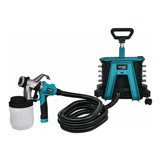
Summary of Contents for BorMann Pro BPG9200
- Page 1 BPG9200 035114 v2.1 Art Nr: WWW.BORMANNTOOLS.COM...
- Page 2 WWW.BORMANNTOOLS.COM...
- Page 3 WWW.BORMANNTOOLS.COM...
- Page 4 WWW.BORMANNTOOLS.COM...
- Page 5 WWW.BORMANNTOOLS.COM...
- Page 6 WWW.BORMANNTOOLS.COM...
- Page 7 WWW.BORMANNTOOLS.COM...
- Page 8 WWW.BORMANNTOOLS.COM...
- Page 9 WWW.BORMANNTOOLS.COM...
- Page 10 WWW.BORMANNTOOLS.COM...
-
Page 11: Safety Instructions
Safety instructions It is important for you to read and understand this manual. The information it contains relates to protecting YOUR SAFETY and PREVENTING PROBLEMS. The symbols below are used to help you recognize this information. Danger! Indicates an imminently hazardous situation which, if not avoided, will result in death or serious injury. Warning! Indicates a potentially hazardous situation which, if not avoided, could result in death or serious injury. - Page 12 To avoid these risks, take the following preventions • Keep electrical cord plug and sprayer trigger free from spray material and other liquids. Never hold cord at plug connections to support cord. Failure to observe may result in an electrical shock. •...
-
Page 13: Operation
Setup Warning! Be sure to use appropriate protective gear and unplug unit. Warning! Make sure area is well ventilated and free of flammable vapours. Aligning the pickup tube (Fig. B) The pickup tube (#15) needs to be aligned in the direction toward the front of the canister ( Fig. B). This will ensure you spray as much material as possible before you need to refill. - Page 14 ON / OFF switch (fig. G) The on/off switch is located on the top of the power unit. Press the switch button to turn on or turn off the power unit. Smart select nozzle selection (Fig. H, Fig. H1) There are three spray patterns to choose from: - Vertical Flat Jet - Horizontal Flat Jet - Circular Jet...
- Page 15 Air cap #3 Spray jet pattern Application Spray Width lever #8 Vertical wide jet for hori- zontal coating direction Large size surface top coating Horizontal wide jet for vertical coating direction Flow control knob (Fig. I) The flow control knob (#19) regulates the amount of liquid that can be sprayed. Turning the flow knob clockwise increases the flow of liquid. Turning the knob counter anti-clockwise decreases the flow of liquid.
-
Page 16: Maintenance
• Unscrew the tip collar (#4) and remove all the parts of the spray nozzle(#3,#4,#5,#6,#7.#8) from the sprayer. Remove the spray tip(#9) from the sprayer ( Fig. Q1). Clean all parts with the cleaning brush in the appropriate cleaning solution (Fig. Q, Fig.Q1). Be sure to clean around check valve with brush (Fig. - Page 17 TROUBLE: TOO MUCH OVER SPRAY. Possible cause Remedy Sprayer too far from surface. Reduce distance to surface. Too much material being sprayed. Reduce flow by turning flow control knob. TROUBLE: LITTLE OR NO MATERIAL BEING RELEASED. Possible cause Remedy Spray nozzle/tip clogged. Clean nozzles.
-
Page 18: Οδηγίες Ασφαλείας
Οδηγίες ασφαλείας Είναι σημαντικό να διαβάσετε και να κατανοήσετε τις οδηγίες αυτού του εγχειριδίου. Οι πληροφορίες που περιέχει σχετίζονται με την προστασία της ΣΩΜΑΤΙΚΗΣ ΣΑΣ ΑΚΕΡΑΙΟΤΗΤΑΣ ΚΑΙ ΤΗΝ ΠΡΟΛΗΨΗ ΤΩΝ ΠΡΟΒΛΗΜΑΤΩΝ. Οι παρακάτω προειδοποιήσεις χρησιμοποιούνται για να σας βοηθήσουν να αναγνωρίσετε... - Page 19 • Φοράτε εξοπλισμό προστασίας των ματιών και της όρασής σας. • Φοράτε τον κατάλληλο ρουχισμό προστασίας όπως απαιτείται από τον κατασκευαστή των υλικών ψεκασμού. Προειδοποίηση! Κίνδυνος ηλεκτροπληξίας. Κίνδυνος πρόκλησης σοβαρού τραυματισμού. Για να αποφύγετε αυτούς τους κινδύνους, λάβετε τα ακόλουθα μέτρα: •...
- Page 20 Περιγραφή βασικών τμημάτων (Εικ. A, Εικ. A1, Εικ. A2 ) 1. Πιστόλι βαφής 16.1 Χιτώνιο βαλβίδας ελέγχου 1 28. Τροχοί με φρένο 2. Μονάδα ισχύος (Ηλεκτροκινητήρας) 16.2 Βαλβίδα ελέγχου 29. Τροχοί χωρίς φρένο 3. '' Έξυπνος'' επιλογέας ακροφυσίου 16.3 Ελατήριο 30.
-
Page 21: Οδηγίες Λειτουργίας
Οδηγίες λειτουργίας Συμβουλές προετοιμασίας Πίνακας οδηγιών σύστασης αραίωσης • Θα πρέπει πάντα να ανακατεύετε και να στραγγίζετε καλά το υλικό πριν από τη χρήση. Υλικό ψεκασμού ''Χρόνος λήξης της • Για οποιαδήποτε εργασία βαφής ή επίχρισης θα πρέπει πάντα να διασφαλίζετε ότι έχετε προ- μέτρησης'' ετοιμάσει... - Page 22 Θέση ''έξυπνου'' επιλογέα Μοτίβο ψεκασμού Θέση ρυθμιστή πλάτους Εφαρμογή/εργασία ψεκασμού #8 Αρχικές επιστρώσεις, Μικρό κυκλικό μοτίβο γωνίες, άκρα και ψεκασμού δυσπρόσιτα σημεία. Κάθετο οβάλ μοτίβο με στενή δέσμη για οριζόντια κατεύθυνση επικάλυψης (''πέρασμα'') Μικρή - μεσαία επιφάνεια Οριζόντιο οβάλ μοτίβο με στενή...
- Page 23 Ανάπτυξη της κατάλληλης τεχνικής ψεκασμού • Εξασκηθείτε στον χειρισμό του πιστολιού βαφής σε ένα χαρτόνι ώστε να δοκιμάσετε το επιλεγμένο μοτίβο ψεκασμού και να εξοικειωθείτε με τη λειτουργία ελέγχου ροής του πιστολιού βαφής. • Βεβαιωθείτε ότι η επιφάνεια του τεμαχίου εργασίας δεν περιέχει σκόνη, υπολείμματα και λιπαρές ουσίες. •...
- Page 24 Συντήρηση Χρησιμοποιήστε μόνο ήπια απορρυπαντικά και ένα ελαφρώς νοτισμένο πανί για να καθαρίσετε τη μονάδα ισχύος. Ποτέ μην αφήνετε κανένα υγρό να εισχω- ρήσει στο εσωτερικό της μονάδας ισχύος. Μην βυθίζετε ποτέ κανένα μέρος της μονάδας ισχύος σε υγρό. Σημαντική σημείωση: Για να διασφαλιστεί η ΑΣΦΑΛΕΙΑ και η ΑΞΙΟΠΙΣΤΙΑ του προϊόντος, οι επισκευές, η συντήρηση και οποιαδήποτε μετατροπή (εκτός από αυτές...
-
Page 25: Τεχνικά Χαρακτηριστικά
Το δοχείο δεν έχει τοποθετηθεί σωστά Συσφίξτε καλά το δοχείο μέχρι να ασφαλίσει στην θέση του Η τάπα ταχείας επαναπλήρωσης δεν έχει τοποθετηθεί σωστά Συσφίξτε καλά την τάπα μέχρι να ασφαλίσει στην θέση της Ο σωλήνας αέρα έχει τομή ή έχει αποσυνδεθεί Έλεγχος...


Need help?
Do you have a question about the Pro BPG9200 and is the answer not in the manual?
Questions and answers