Advertisement
Quick Links
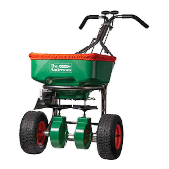
MODEL #DI2020
MODEL #DI2020
Thank you!
You have purchased the highest quality professional
broadcast spreader on the market. Featuring an
advanced design duel impeller system. This spreader
provides a symmetrical spread pattern, eliminating the
potential for uneven application. The dual impeller design
provides superior flexibility in spreading a variety of
granule types and seeds. A single adjustment of the rate
plate is all that is required to deliver a uniform application
each time.
Helpful Hints
While your spreader is mostly assembled, to minimize
shipping costs, you will need to attach the tires, frame
rest, upper handle, and control rods.
Before you begin, you will need the following tools to
assemble your DI2020 spreader:
Two 7/16" box wrenches,
One 1/2"
One 3/8" box wrench
The hardware kit include additional spare hardware:
- Cotter pin (for retaining tire)
- (2) 2 ¼" stainless bolts
- (2) ¼" stainless nuts
P80000_M52098_Rev_June2020
Professional 75lb Dual Impeller
Professional 75lb Dual Impeller
Broadcast Spreader
Broadcast Spreader
ASSEMBLY INSTRUCTIONS
ASSEMBLY INSTRUCTIONS
IN THE BOX
(2) Control Rods
(1) Deflector
Control
Rod
(1) Upper Handle
Assembly
60368
(1) Hopper
Frame
Assembly
Other Items:
(1) Rain cover
(1) Hopper screen
(1) Hardware pack
(1) Frame Rest
79008
(2) Tires
P15043
PAGE 1
Advertisement

Subscribe to Our Youtube Channel
Related Manuals for The Andersons DI2020


Summary of Contents for The Andersons DI2020
- Page 1 (1) Hopper Before you begin, you will need the following tools to Frame assemble your DI2020 spreader: Assembly Two 7/16” box wrenches, One 1/2” One 3/8” box wrench...
- Page 2 ASSEMBLY & OPERATIONS MANUAL ASSEMBLY: 20 minutes STEP 1: Remove from the box and set aside the STEP 4: Start with the inboard (A) tire and insert hardware pack containing control rods, deflector rod, (4.1) the wheel spring clip through the hole of the and calibrator keys.
- Page 3 ASSEMBLY & OPERATIONS MANUAL ASSEMBLY: continued STEP 6: Position the spreader laying forward on wheels and hopper as shown in Figure 6.3. Figure 6.4 - Remove the cross brace by removing two bolts and lock nuts. Keep the hardware for reinstallation in step 6.6.
- Page 4 ASSEMBLY & OPERATIONS MANUAL ASSEMBLY: 20 minutes STEP 7: Position the spreader upright on wheels. Place handles inside of the rest as shown in the outlined box below and pull upward to mate the handle in place with the rest. Attach the upper handle to the frame rest installed in Step 6 using four (7.1) 1/4”...
- Page 5 ASSEMBLY & OPERATIONS MANUAL ASSEMBLY: 20 minutes STEP 8.1: Attach control rods to spreader shut off pivots. Install one 5/16” hex nut (8.1) on each control rod as close as possible, to the halfway point of the threaded portion. Look at the rods and make sure the initial nut is threaded equally up the rod, this is to give you a clean starting point for calibration.
- Page 6 ASSEMBLY & OPERATIONS MANUAL STEP 9: Install the 2” long deflector spring (9.1) onto the coined end of the deflector control rod (9.2). Insert deflector control rod through the bottom of the bracket mounted on upper handle assembly. Place deflector control rod grip (9.3) on the top end of the deflector control rod.
- Page 7 ASSEMBLY & OPERATIONS MANUAL STEP 9 <continued> Insert lower portion of deflector control rod through the metal slot attached to deflector shield. With deflector in the raised position, insert the deflector control rod from outboard position towards the inboard position and through metal loop. Secure rod with infinity spring clip (9.4).
- Page 8 ASSEMBLY & OPERATIONS MANUAL CALIBRATION: 10 minutes STEP 13: Your spreader should be calibrated before first use. Once complete, the spreader should not need further calibration unless the spreader is disassembled or damaged. 13.1 STEP 13.1: If the pointer is not set at setting “I”, pull 13.2 both shut off handles back to the closed position.
- Page 9 ASSEMBLY & OPERATIONS MANUAL STEP 15: Start with left hand lever. Push the lever forward to “open” position. See Image (15.1) below. Verify the opening Flat side towards size using one of your calibration keys shown in image (15.2). handlebars 15.1 Key cross section 15.2...
-
Page 10: Operation
OPERATION: 1) Check product bag for the desired rate setting and 4) The settings on the product label are only swath width. The DI2020 uses the same rate setting recommended starting points for calculating letter as the following Anderson models: product application rate. -
Page 11: Parts List
WARRANTIES, INCLUDING WITHOUT LIMITATION ANY IMPLIED WARRANTY OR MERCHANTABILITY OR FITNESS OR INTENDED USE FOR A PARTICULAR PURPOSE AND OF ANY OTHER OBLIGATION ON THE PART OF The Andersons. The Andersons SHALL NOT BE LIABLE FOR ANY INCIDENTAL, SPECIAL OR CONSEQUENTIAL LOSS, DAMAGE OR EXPENSE DIRECTLY OR INDIRECTLY ARISING...
Need help?
Do you have a question about the DI2020 and is the answer not in the manual?
Questions and answers