Table of Contents
Advertisement
Quick Links
Advertisement
Table of Contents

Subscribe to Our Youtube Channel
Related Manuals for HIKVISION DS-D4425FI-CKF


Summary of Contents for HIKVISION DS-D4425FI-CKF
- Page 1 Full-Color LED Display Unit Installation Guide...
- Page 2 INTERRUPTION, OR LOSS OF DATA, CORRUPTION OF SYSTEMS, OR LOSS OF DOCUMENTATION, WHETHER BASED ON BREACH OF CONTRACT, TORT (INCLUDING NEGLIGENCE), PRODUCT LIABILITY, OR OTHERWISE, IN CONNECTION WITH THE USE OF THE PRODUCT, EVEN IF HIKVISION HAS BEEN ADVISED OF THE POSSIBILITY OF SUCH DAMAGES OR LOSS.
- Page 3 Full-Color LED Display Unit Installation Guide PRODUCTION OF CHEMICAL OR BIOLOGICAL WEAPONS, ANY ACTIVITIES IN THE CONTEXT RELATED TO ANY NUCLEAR EXPLOSIVE OR UNSAFE NUCLEAR FUEL-CYCLE, OR IN SUPPORT OF HUMAN RIGHTS ABUSES. IN THE EVENT OF ANY CONFLICTS BETWEEN THIS MANUAL AND THE APPLICABLE LAW, THE LATER PREVAILS.
- Page 4 Full-Color LED Display Unit Installation Guide Regulatory Information FCC Information Please take attention that changes or modification not expressly approved by the party responsible for compliance could void the user's authority to operate the equipment. FCC compliance: This equipment has been tested and found to comply with the limits for a Class A digital device, pursuant to part 15 of the FCC Rules.
- Page 5 Full-Color LED Display Unit Installation Guide 2006/66/EC (battery directive): This product contains a battery that cannot be disposed of as unsorted municipal waste in the European Union. See the product documentation for specific battery information. The battery is marked with this symbol, which may include lettering to indicate cadmium (Cd), lead (Pb), or mercury (Hg).
- Page 6 Full-Color LED Display Unit Installation Guide Preface Applicable Model This manual is applicable to full-color LED display units for installation guidance. Symbol Conventions The symbols that may be found in this document are defined as follows. Symbol Description Indicates a hazardous situation which, if not avoided, will or could Danger result in death or serious injury.
- Page 7 Full-Color LED Display Unit Installation Guide ● Ensure correct wiring of the terminals for connection to an AC mains supply. ● The equipment has been designed, when required, modified for connection to an IT power distribution system. ● Install the equipment according to the instructions in this manual. ●...
-
Page 8: Table Of Contents
Full-Color LED Display Unit Installation Guide Contents Chapter 1 Product Introduction ....................1 1.1 Overview ..........................1 1.2 Product Components......................1 Chapter 2 Rack Installation ......................2 2.1 About Rack ..........................2 2.2 Install the Rack ........................2 2.2.1 Precautions ......................... 2 2.2.2 Install the Wall-Mounted Rack .................. -
Page 9: Chapter 1 Product Introduction
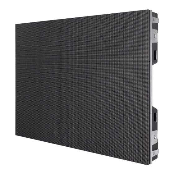
Full-Color LED Display Unit Installation Guide Chapter 1 Product Introduction 1.1 Overview Full-color LED display unit (hereinafter referred to as the device, the product, or the LED) is a high- precision product delivering clear and vivid images. It is featured by wide color gamut, stable performance, long service life, strong environmental adaption, cost effective, and little cost to use. -
Page 10: Chapter 2 Rack Installation
Full-Color LED Display Unit Installation Guide Chapter 2 Rack Installation 2.1 About Rack There are three types of racks for installing our full-color LED products: wall-mounted rack, ultrathin rack and all-in-one rack. The wall-mounted rack is used for installing front-maintenance cabinets only. - Page 11 Full-Color LED Display Unit Installation Guide Figure 2-1 Assemble the Base Frame Figure 2-2 Base Frame Assembled 2. Use expansion bolts, T-Shaped bolts, and fixing plates to fix the base frame onto the wall. Figure 2-3 Fix the Base Frame onto the Wall Install the Rack Frame Steps 1.
- Page 12 Full-Color LED Display Unit Installation Guide Figure 2-4 Assemble the Rack Frame 2. Use expansion bolts, T-Shaped bolts, and fixing plates to fix the rack frame onto the wall.
- Page 13 Full-Color LED Display Unit Installation Guide Figure 2-5 Fix the Rack Frame onto the Wall Install Cabinets into the Rack Frame After base frame and rack frame are well installed, perform the following steps to install the cabinets into the rack frame: Steps 1.
- Page 14 Full-Color LED Display Unit Installation Guide Figure 2-6 Fix the Screen...
- Page 15 Full-Color LED Display Unit Installation Guide Figure 2-7 Screen Fixed 2. Install the cabinets from the center to both sides until cabinets of the first row installed. Figure 2-8 Screens Fixed 3. Repeat the above steps to install the other cabinets in the above rows.
- Page 16 Full-Color LED Display Unit Installation Guide 4. Use a level to measure and ensure that the cabinets are flat and vertical. Note ● Do not fix the screws between the connectors and cabinets too tight for future adjustment. ● In normal cases, you should lock out LED lamp boards after they are adjusted horizontally and vertically because the boards will probably be moved during the installation of other lamp boards.
-
Page 17: Install The Ultrathin Rack
Full-Color LED Display Unit Installation Guide Figure 2-10 Screen Installation Finished Note ● Install the device no more than 5 mm away from the wall or other metal racks in case of lamp board drop resulting in electric shock. ● After installation, there should be no openings around the LED module. The bottom bracket under the wire outlet position should completely cover the bottom hole only to let the wire out, to prevent the molten material from dripping to the bottom during fire caused by internal failure. - Page 18 Full-Color LED Display Unit Installation Guide Figure 2-11 Assemble the Base Frame Unit Figure 2-12 Base Frame Unit Assembled 2. Use wedge-locking collector bolts to connect the base frame units. Figure 2-13 Connect the Base Frame Units 3. Position the anchor bolts into the base frame and tighten the bolts.
- Page 19 Full-Color LED Display Unit Installation Guide Figure 2-14 Assemble the Base Frame 4. Level the bottom chassis and then tighten the bolts. Figure 2-15 Leveled Bottom Chassis Install the Rack Frame Steps 1. Use header corners to connect aluminum extrusion rods from bottom to top.
- Page 20 Full-Color LED Display Unit Installation Guide Figure 2-16 Assemble the Rack Frame Unit 2. Use wedge-locking collector bolts to connect the rack frame units. Figure 2-17 Connect the Rack Frame Units 3. Align the rack frame to the base chassis and use wedge-locking collector bolts to fix the frames.
- Page 21 Full-Color LED Display Unit Installation Guide Figure 2-18 Align the Rack Frame to the Base Chassis Figure 2-19 Frames Aligned...
- Page 22 Full-Color LED Display Unit Installation Guide Install the Rear Pulling Rods (for Large-scale Project) Steps 1. Use the wedge-locking collector bolts to fix the rear pulling rods into the rack frame. Figure 2-20 Fix the Rear Pulling Rods into the Rack frame...
- Page 23 Full-Color LED Display Unit Installation Guide Figure 2-21 Rear Pulling Rods Fixed 2. Use the expansion bolts to fix the rear pulling rods onto the bearing wall. Figure 2-22 Fix the Rear Pulling Rods onto the Bearing Wall...
- Page 24 Full-Color LED Display Unit Installation Guide Install the Connectors The connectors are divided into two parts: customized front joint piece which is used to connect the screens, and back connecting component which is used to connect the rack frame. The following figures list three types of connectors and the positions where the connectors used respectively.
- Page 25 Full-Color LED Display Unit Installation Guide Steps 1. Twist the hexagonal screws into the T-Shaped nuts. 2. Insert the T-Shaped nuts into the slots of aluminum extrusion rods, and move the connectors to the suitable place. Figure 2-25 Install the Connectors 3.
- Page 26 Full-Color LED Display Unit Installation Guide Figure 2-26 Fix the Screen with Joint Pieces Note ● Install the cabinets from the bottom to the top, from the middle to the sides. ● Do not fix the screws between the connectors and cabinets too tight for future adjustment. ●...
- Page 27 Full-Color LED Display Unit Installation Guide 3. Use a level to measure and ensure that the cabinets are flat and vertical. Note When there is a deviation in height, simply place a thin iron sheet under the bottom. Do not try to resolve the deviation by hitting the cabinets on the top because it will result in larger deviation later.
-
Page 28: Install The All-In-One Rack
Full-Color LED Display Unit Installation Guide Figure 2-29 Screen Installation Finished Note ● For details about cabinet stitching, see Stitch Cabinet Frames. ● For details about lamp board installation, see Install Lamp Boards on the Cabinets. 2.2.4 Install the All-in-One Rack The all-in-one racks are used for mounting front-maintenance products and back-maintenance products. - Page 29 Full-Color LED Display Unit Installation Guide Figure 2-30 Assemble the Base Frame Unit Figure 2-31 Base Frame Unit Assembled 2. Use wedge-locking collector bolts to connect the base frame units.
- Page 30 Full-Color LED Display Unit Installation Guide Figure 2-32 Connect the Base Frame Units Figure 2-33 Base Frame Units Connected 3. Repeat the above steps to connect the other base frame units.
- Page 31 Full-Color LED Display Unit Installation Guide Figure 2-34 Base Frame 4. Position the anchor bolts into the base frame and tighten the bolts. Figure 2-35 Assemble the Base Frame 5. Level the bottom chassis and then tighten the bolts. Figure 2-36 Leveled Bottom Chassis Install the Rack Frame Steps 1.
- Page 32 Full-Color LED Display Unit Installation Guide Figure 2-37 Assemble the Rack Frame Unit 2. Use wedge-locking collector bolts to connect the rack frame units.
- Page 33 Full-Color LED Display Unit Installation Guide Figure 2-38 Connect the Rack Frame Units 3. Repeat the above steps to connect the other rack frame units. Figure 2-39 Rack Frame 4. Align the rack frame to the base chassis and use wedge-locking collector bolts to fix the frames.
- Page 34 Full-Color LED Display Unit Installation Guide Figure 2-40 Align the Rack Frame to the Base Chassis Figure 2-41 Frames Aligned Install the Rear Pulling Rods (for Large-scale Project) Steps 1. Use the wedge-locking collector bolts to fix the rear pulling rods into the rack frame.
- Page 35 Full-Color LED Display Unit Installation Guide Figure 2-42 Fix the Rear Pulling Rods into the Rack Frame Figure 2-43 Rear Pulling Rods Fixed 2. Use the expansion bolts to fix the rear pulling rods onto the bearing wall.
- Page 36 Full-Color LED Display Unit Installation Guide Figure 2-44 Fix the Rear Pulling Rods onto the Bearing Wall Install the Connectors The connectors are divided into two parts: customized front joint piece which is used to connect the screens, and back connecting component which is used to connect the rack frame. The following figures list three types of connectors and the positions where the connectors used respectively.
- Page 37 Full-Color LED Display Unit Installation Guide Figure 2-46 Connectors Installed Note Please pay attention to the types of outermost connectors between rack frame and bottom chassis. Steps 1. Twist the hexagonal screws into the screw thread plates. 2. Insert the screw thread plates into the slots of aluminum extrusion rods, and move the connectors to the suitable place.
- Page 38 Full-Color LED Display Unit Installation Guide Install Cabinets into the Rack Frame After the bottom chassis, rack frame, and connectors are well installed, perform the following steps to install the cabinets into the rack frame: Steps 1. Install the first cabinet from the lower middle part. Level and secure the cabinet to the connectors on the rack frame.
- Page 39 Full-Color LED Display Unit Installation Guide Figure 2-49 Fix the Screens 3. Use a level to measure and ensure that the cabinets are flat and vertical. Note When there is a deviation in height, simply place a thin iron sheet under the bottom. Do not try to resolve the deviation by hitting the cabinets on the top because it will result in larger deviation later.
- Page 40 Full-Color LED Display Unit Installation Guide Figure 2-50 Screens Fixed 5. Ensure that all the cabinets are flat and vertical and the seams between the cabinets are even. Then tighten the anchor bolts to complete the installation.
- Page 41 Full-Color LED Display Unit Installation Guide Figure 2-51 Screen Installation Finished Note ● For details about cabinet stitching, see Stitch Cabinet Frames. ● For details about lamp board installation, see Install Lamp Boards on the Cabinets. Install the Cover Plates and Door Plates for Bottom Chassis Steps 1.
- Page 42 Full-Color LED Display Unit Installation Guide Figure 2-52 Install the Cover Plates 2. Use T-shaped bolts or door hinge to install the door plates including upper fixing plates, lower fixing plates, left door plates, and right door plates. Figure 2-53 Install the Door Plates...
-
Page 43: Chapter 3 Cabinet Installation
Full-Color LED Display Unit Installation Guide Chapter 3 Cabinet Installation 3.1 Introduction 3.1.1 About the Cabinet A cabinet is a basic unit for LED engineering installation in which LED modules are neatly mounted on a metal sheet (cast aluminum) box, with a built-in independent receiving card and switching power supply, an engineering installation structure, and independent display. -
Page 44: Install The Cabinets
Full-Color LED Display Unit Installation Guide ● If your video wall has more than 15 rows (220 V) or 7 rows (110 V) of LED displays, connect 2 power cords to each column both from the bottom of the lowest display. That is, use 2 power cords for each column. - Page 45 Full-Color LED Display Unit Installation Guide Figure 3-1 Locating Studs, Locating Holes and Installation Holes Stitch Cabinet Frames Horizontally Steps 1. Align the installation holes in the horizontal direction of the two adjacent cabinet frames, and adjust the cabinet frames to the relative level.
- Page 46 Full-Color LED Display Unit Installation Guide 2. Use M10 hexagon wrench to secure the bolts. Figure 3-2 Cabinet Stitching Horizontally Note ● Each cabinet has 2 reserved bolts on the left side. ● Secure the adjacent cabinets from right to left. ●...
-
Page 47: Install Lamp Boards On The Cabinets
Full-Color LED Display Unit Installation Guide Figure 3-3 Cabinet Stitching Vertically Note ● Each cabinet has 2 reserved bolts at the bottom. ● Secure the adjacent cabinets from up to down. ● Adjust the flatness of the cabinet frames to ensure the horizontal and vertical alignment between the cabinet frames. - Page 48 Full-Color LED Display Unit Installation Guide Figure 3-4 Front and Back of the Lamp Board Fix the lamp boards on the cabinet frames by magnetic attraction. One cabinet frame is equipped with 6 lamp boards. It is recommended to connect and install the 6 lamp boards for each cabinet from down to up and right to left (as the figure shown below).
- Page 49 Full-Color LED Display Unit Installation Guide Note ● The signal cable connection varies with different pixel pitches and signal input modes for lamp boards. The figures below show different connections for different kinds of lamp boards. Numbers on the interfaces indicate which lamp board should be connected to (lamp boards serial number refer to Figure 3-5).
- Page 50 Full-Color LED Display Unit Installation Guide Figure 3-7 Signal Cable Connection (P1.8 and P2.5) 2. Place the lamp boards on the front of the cabinet frames, and align the lamp boards and the edge of the cabinet frames initially. Note Please align the connector and pay attention to the direction of lamp boards when adsorbing the lamp board.
-
Page 51: Install Protective Shield
Full-Color LED Display Unit Installation Guide Figure 3-8 Lamp Board Installation Completed 4. Optional: If you need to remove the lamp boards, remove the first lamp board by using the LED vacuum pumping tool, and remove other lamp boards with hands. Figure 3-9 LED Vacuum Pumping Tool 3.2.5 Install Protective Shield To reduce the risk of electric shock, install protective shield on the exposed connector after... - Page 52 Full-Color LED Display Unit Installation Guide ● The power cable of LED screen should be grounded before powering on the screen. ● Before installing the protective shield, ensure that the power is cut off.
-
Page 53: Adjust Lamp Boards On The Cabinets
Full-Color LED Display Unit Installation Guide 3.2.4 Adjust Lamp Boards on the Cabinets Rotate the iron pieces on the cabinet frames to push the adjusting points and lamp boards out until the cabinet is level with others. In the following figure, all the circled points are adjusting points, and there are 12 adjusting points for each cabinet. - Page 54 Full-Color LED Display Unit Installation Guide Figure 4-1 Login Interface 2. Click Online Device to search for online devices. 3. Activate the desired online device. ● If the device is not activated, activate the device and set a password. ● If the device is activated, enter the password to log in. ●...
-
Page 55: Configure Screen Attributes
Full-Color LED Display Unit Installation Guide Note The default username is admin, password is admin12345, and port is 8000. 4.2 Configure Screen Attributes Configure screen scale, type, and resolution. You can also select signal source type as needed. Steps 1. Go to Basic Configuration → Display Attribute. Figure 4-3 Display Attributes 2. - Page 56 Full-Color LED Display Unit Installation Guide Note Undo check Display Actual Lines on Screen after signal cable configuration finished and saved. 3. Select sending port below Please select sending port to connect. Note Connect screens in accordance with the position prompt of each screen. If the position prompt shows 2-1, it indicates that the screen is the first screen connected to No.2 sending port.
- Page 57 UD25946B...
Need help?
Do you have a question about the DS-D4425FI-CKF and is the answer not in the manual?
Questions and answers