Table of Contents
Advertisement
Quick Links
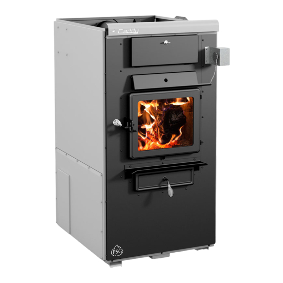
Installation and operating instructions
for the CADDY WOOD FURNACE
FURNACE MODELS INCLUDED IN THIS MANUAL
WOOD
ADD-ON
Read these instructions carefully before installing
You have purchased one of the finest wood or combination furnaces
available on the market. We are confident that your furnace will provide
Verified and tested for Canada and
the United States by an accredited
laboratory.
Eco-energy at the hearth
of your home
Printed in Canada
(PF01015 model)
Certified according to CSA B415.1-10, CSA B366.1, UL391,
CSA C22.2 NO.236, UL 1995, CAN/CSA B140.4 AND UL 727
WOOD
ONLY
and operating your furnace.
CONGRATULATIONS!
years of comfort and safe operation.
Please keep this document!
COMBINATION
15kW /18kW / 20 kW
This
manual is
available for
manufacturer's web site. It is a copyrighted document. Re-sale
is strictly prohibited. The manufacturer may update this manual
from time to time and cannot be responsible for problems,
injuries, or damages arising out of the use of information
contained in any manual obtained from unauthorized sources.
St-Augustin-de-Desmaures (Quebec)
AND OIL
free
download
PSG
250, de Copenhague,
CANADA G3A 2H3
14-02-2020
on the
45831A
Advertisement
Table of Contents

Related Manuals for CADDY PF01015

Summary of Contents for CADDY PF01015
- Page 1 Installation and operating instructions for the CADDY WOOD FURNACE (PF01015 model) Certified according to CSA B415.1-10, CSA B366.1, UL391, CSA C22.2 NO.236, UL 1995, CAN/CSA B140.4 AND UL 727 FURNACE MODELS INCLUDED IN THIS MANUAL COMBINATION WOOD WOOD 15kW /18kW / 20 kW...
-
Page 2: Table Of Contents
OPERATING INSTRUCTIONS ............................21 ELECTRICAL DIAGRAM FOR SERIAL FURNACE (VIA CONTROL) ..................22 ELECTRICAL DIAGRAM FOR SERIAL FURNACE (VIA MOTOR) ..................24 CADDY WOOD ONLY FURNACE OR COMBINED WOOD / ELECTRIC OR PARALLEL ADD-ON PF01015 ........ 26 INSTALLATION INSTRUCTIONS ............................27 14.1. - Page 3 15.2. HEATPUMP INSTALLATION ............................48 CONFIGURATION AND OPERATING INSTRUCTIONS ......................49 16.1. CONTROLS SYSTEM ..............................49 16.2. SYSTEM CONFIGURATION ............................49 16.3. TOUCH SCREEN ................................50 16.3.1. ICONS DESCRIPTION ..............................50 16.3.2. LANGUAGE SELECTION AND TEMPERATURE UNIT....................50 16.4. ADDING AUXILIARY HEATING SOURCE AND SELECTION OF OPTIONS ..............51 16.4.1.
- Page 4 28.6.1. COMBUSTION VERIFICATION PROCEDURE: ......................74 28.6.2. ELECTRODES SETTING ..............................75 28.7. APPLIANCE START-UP ..............................76 28.8. PROLONGED CLOSING ..............................76 TECHNICAL DATA ................................... 76 29.1. UH –CADDY ..................................... 76 MAINTENANCE ..................................77 30.1. MAINTENANCE ................................77 30.2. SERVICE ..................................77 30.3.
-
Page 5: Introduction
The Caddy furnace was tested and approved according to the CSA B415.1-10 Standard. To optimize the efficiency of your furnace, here is some advice that you should follow when installing or operating your Caddy. - Page 6 2. APPLIANCE PERFORMANCE Fuel type Dry cordwood Recommended heating area[*] 1,000 to 2,500 ft² (92.90 à 232.25 m²) Firebox volume 3.6 ft³ (0.102 m³) Maximum burn time[*] 15 h Maximum input capacity (dry cordwood) 310,000 BTU Overall heat output rate (min. to max.) 15,436 BTU/h to 49,638 BTU/h (4.5 kW to 14.5 kW) Nominal heat output at 15lb/ft³...
-
Page 7: General Features
3. GENERAL FEATURES Maximum log length 22 in (559 mm) / north-south* Diameter of the flue collar 6 in (152 mm) Recommended connector pipe diameter 6 in (152 mm) (wood only or combined wood-electric) Mandatory connector pipe diameter 7 in (178 mm) (combined wood-oil) Recommended chimney diameter 6 in (152 mm) (wood only or combined wood-electric) Mandatory chimney diameter... -
Page 8: Specifications
4. SPECIFICATIONS Color Grey Thermostatic control Door type Single, glass with cast iron frame Glass type Ceramic glass Air return plenum – dimensions (Depth or Height) 15 3/4 in Air return plenum – dimension (Width) 24 3/4 in Hot air plenum – dimensions (Depth or Height) 28 5/8 in Hot air plenum –... -
Page 9: Caddy Furnace Technical Data
5. CADDY FURNACE TECHNICAL DATA THEORETICA TEMP MODEL (DIRECT DRIVE) STATIC PRESSURE FILTER L DEBIT VAR. VENT MOT. VIT. (CFM) (OF) MIN. MAX. CADDY WITH BLOWER / CADDY DD-10 1,900 25" x 14" x 1" ADD-ON (PARALLEL) CADDY ADD-ON N/AP... - Page 10 ADD-ON WOOD ONLY, WOOD/ELECTRIC, WOOD/OIL...
-
Page 11: Chimney And Draft
This furnace must be connected to a chimney certified for use with wood burning heating appliances. A 7-inch chimney and connector are mandatory for the Caddy if it is used as a wood-oil unit or if an oil option may be installed in the future. -
Page 12: Smoke Detector
N.B.: To minimize the frequency of the chimney cleaning, buy your firewood at least one year before using it. Store it in a dry place in order to obtain the minimum moisture rate and optimize the efficiency. Do not store wood or combustible materials within the installation minimum clearances or the space required to reload the appliance and remove ashes. -
Page 13: Caddy Add-On (Serial Installation) Pf01015
INSTALLATION AND OPERATION INSTRUCTIONS CADDY ADD-ON (SERIAL INSTALLATION) PF01015... -
Page 14: Safety Precaution
WITH CGA STANDARD CAN/CGA-2.3 OR ITS PRECEDENTS. 10. INTRODUCTION The wood burning Caddy Add-on furnace is approved for in-line connection to an existing oil furnace or any gas or electric furnace with a maximum heating capacity of 120,000 BTU/h. (35.17 kW) 10.1. - Page 15 OPTION 3 and OPTION 4 are permitted when installing the Caddy furnace with en existing furnace whose hot air plenum ducts are downwards flowing. The hot air plenum of the Caddy furnace must be above the furnace and cannot be directed downward.
- Page 16 Option 3 Option 4...
- Page 17 EXAMPLE 1 EXAMPLE 2...
-
Page 18: Parallel Installation
You must determine the air flow through the existing furnace before installing the Caddy wood add-on: 1. Run the furnace to which the Caddy add-on is connected until it reaches its regular heating temperature. 2. With a thermometer, measure the temperature of the fresh air entering the furnace and that of the air exiting the furnace in the hot air plenum. -
Page 19: Minimum Clearances To Combustible Materials
11.3.1. MINIMUM CLEARANCES TO COMBUSTIBLE MATERIALS MINIMUM CLEARANCES 29" (737 mm) 8" (204 mm) 18" (458 mm) 6" (153 mm) 6" (153 mm) 24" (610 mm) 1" (26 mm) 72" (1 829 mm) 18" (458 mm) 11.3.2. MINIMUM CLEARANCES TO COMBUSTIBLES MATERIALS FOR AIR RETURN DUCT See Section 14.7.2 - MINIMUM CLEARANCES TO COMBUSTIBLES MATERIALS FOR AIR RETURN DUCT 11.3.3. -
Page 20: Installing The Connecting Duct From The Existing Furnace
11.4. INSTALLING THE CONNECTING DUCT FROM THE EXISTING FURNACE To install the connecting duct from the existing furnace on the left or right side of your CADDY Add-on furnace, remove the screws (A) securing the large panel (B or C) of the furnace. Connect the ducts. -
Page 21: Servomotor Installation
11.7. SERVOMOTOR INSTALLATION See Section 14.5 - SERVOMOTOR INSTALLATION AND CONNECTION 11.8. THERMOSTAT INSTALLATION See Section 15 - THERMOSTAT INSTALLATION 11.9. OPERATING INSTRUCTIONS Operate the existing furnace periodically to ensure that it will operate satisfactorily when needed. On the wood furnace, the thermostat controls the air inlet damper. When the thermostat calls for heat, the damper opens and the combustion is stirred up. -
Page 22: Electrical Diagram For Serial Furnace (Via Control)
12. ELECTRICAL DIAGRAM FOR SERIAL FURNACE (VIA CONTROL) Important Note: It is essential to use the three (3) SBI # 51035 relays to make the connection as in 3-relay diagrams. It is possible to use two relay White Rodger (SPNC / SPNO # 90-380) for the two-relay diagram. The use of another brand or model of relay is not recommended since very limited technical support may be provided. - Page 23 REQUIRES 2 RELAY SPNO/SPNC (WHITE ROGERS P/N 90-380) (NOT INCLUDED) AND 24V AVAILABLE ON EXISTING FURNACE.
-
Page 24: Electrical Diagram For Serial Furnace (Via Motor)
13. ELECTRICAL DIAGRAM FOR SERIAL FURNACE (VIA MOTOR) REQUIRES 1 RELAY (51035) WITH 1 JUNCTION BOX (NOT INCLUDED). - Page 25 REQUIRES 2 RELAY SPNO/SPNC (WHITE ROGERS P/N 90-380) WITH 1 JUNCTION BOX (NOT INCLUDED) AND 24V AVAILABLE ON EXISTING FURNACE.
-
Page 26: Caddy Wood Only Furnace Or Combined Wood / Electric Or Parallel Add-On Pf01015
INSTALLATION AND OPERATION INSTRUCTIONS FOR CADDY WOOD ONLY FURNACE OR COMBINED WOOD / ELECTRIC OR PARALLEL ADD-ON PF01015 CADDY FURNACE – WOOD ONLY CADDY FURNACE – COMBINED WOOD/ELECTRIC... -
Page 27: Installation Instructions
Inspect the furnace to make sure that nothing has been damaged in the shipping. Pull out the wiring kit and the instructions manual from the firebox of the furnace and the accessories from the flue pipe. The following section contains installation instructions for the caddy wood only, caddy wood / electric and caddy add- on parallel configurations. - Page 28 Remove the four screws on the furnace, located on the side of the desired installation. Align the holes of the board housing the holes on the side of the furnace. Use the screws removed in the previous step to secure the housing to the furnace.
- Page 29 Take the telecommunication wire and pull it through the grommet located on the side where the housing board is installed. Once the telecommunication wire is out on the desired side, run it along the back of the furnace and pass it through the grommet at the bottom of link board...
- Page 30 Your furnace should also be connected to a 115V power source. To do so, open the cover power board housing. Connect the power cord to the terminals (Neutral) (Ground) L (Line). Refer to wiring diagram for connecting components. When done, secure the wires with a BX connector (not included) and replace the blower box cover.
-
Page 31: Touchscreen Installation And Connection
14.3. TOUCHSCREEN INSTALLATION AND CONNECTION The touch screen is used to operate the system. It must be installed on the support provided at the back of the furnace, on the same side as the link board housing. Connect link board with the touch screen using the telecommunication wire provided with the user manual. Plug the telecommunication wire in connector labeled LCD and pull it out of the board housing through the top grommet. -
Page 32: Hot Air Plenum Temperature Probe Installation And Connection (Rtd)
14.4. HOT AIR PLENUM TEMPERATURE PROBE INSTALLATION AND CONNECTION (RTD) On the Caddy, a RTD has to be installed on the side of the furnace using the support provided with the unit. The RTD is a sensor that reads the temperature inside the hot air plenum. It is critical to the good operation of the furnace. Refer to electric diagram for connection details. -
Page 33: Servomotor Installation And Connection
14.5. SERVOMOTOR INSTALLATION AND CONNECTION Your Caddy furnace is equipped with a servomotor. To install it, simply screw it in place in the two pre-drilled holes in the front of the furnace using two screws as shown below. -
Page 34: Unit Location
Once installed, install the chain linking the servomotor with the air inlet damper as shown above. The chain must have a set of 1/8". When there is no call for heat, the air inlet damper must be completely closed and the chain must be hooked to the servomotor at the “8 o’clock”... -
Page 35: Minimum Clearances To Combustible Materials
14.7.1. MINIMUM CLEARANCES TO COMBUSTIBLE MATERIALS MINIMUM CLEARANCES 24" (610 mm) 8" (204 mm) 18" (458 mm) 6" (153 mm) 6" (153 mm) 24" (610 mm) 1" (26 mm) 72" (1 829 mm) 18" (458 mm) 14.7.2. MINIMUM CLEARANCES TO COMBUSTIBLES MATERIALS FOR AIR RETURN DUCT The return air duct should be at least equal in size to the return air plenum. -
Page 36: Floor Protection
14.7.4. FLOOR PROTECTION If the floor is made of non-combustible material, no floor protector is required. If the floor is made of combustible material, a non- combustible material floor protector is required (see table below). FLOOR PROTECTION* CANADA 18" (457 mm) 16"... -
Page 37: Flue And Barometric Draft Control Connection
The flue outlet on the Caddy furnace is 6" in diameter and the wood only or wood/electric models may be installed with a 6" chimney approved for use with wood burning heating appliances (2100°F). However, the use of a 7" chimney is mandatory if the retrofit to a wood/oil configuration is probable. -
Page 38: Electrical Connections
Direct connection: solid fuel units can be connected directly to a source of new combustion air only if they are certified for this kind of installation, which must respect the manufacturer’s instructions. The Caddy can be installed with an optional sealed fresh air kit that has been tested with the unit. Consult your dealer. -
Page 39: Hot Air Plenum
informed that the ventilation system may have to be rebalanced by a ventilation technician after the installation of the solid fuel unit. NOTE: It is recommended to install an outside air inlet with a diameter of at least 4" in the room where the heating appliance is installed (see drawing below). -
Page 40: Parallel Installation
PARALLEL INSTALLATION The installation of the Caddy with another furnace using the same ductwork is not allowed in Canada. This type of installation is only allowed in the United States. Ideally, the maximum BTU input of the existing oil, gas, or electric furnace should be equal or higher than the maximum BTU input of the wood furnace. - Page 41 Caddy link board. This way, when a heating signal is sent to the existing furnace, the Caddy receives the same signal. It will tell the Caddy to either not start or, to go into a shut down cycle, if the furnace was already heating when the demand for heat was sent.
-
Page 42: Electrical Element Installation (Optional)
CADDY When a heat signal from the existing furnace’s thermostat will be sent, the Caddy furnace will shut itself down and an envelope will appear on the LCD screen indicating that the existing furnace has taken over. This envelope will disappear as soon as the heat signal of the existing furnace’s thermostat will stop and the Caddy furnace will resume... - Page 43 OUTPUT TEMP. VAR. TOTAL AMPERAGE ALIMENT. VOLTAGE # OF ÉLÉMENTS MODEL BTU/H BREAKER (CFM) (OF) CALIBRE 1 PHASE 15 kW 1,300 51195 120/240 3 – 5 kW 2 – 5 kW, 18 kW 1,300 61434 120/240 2 – 4 kW 20 kW 1,300 68260...
-
Page 44: Thermostat Installation
15. THERMOSTAT INSTALLATION 15.1. WOOD FURNACE ONLY The furnace must be connected to a thermostat. You can use the one provided with the unit or use one that is already installed in your home. The thermostat must be installed on an inside wall and located where it is not likely to be affected by the draft coming from an air outlet. -
Page 45: Combination Wood-Electric Or Wood-Oil Furnace
Once wired to the furnace, it is possible to check the signals from the wall thermostat. On the touch screen main menu, select "TROUBLESHOOT LINK" on page 1 as shown below. When a signal is sent from the thermostat, the circle corresponding to the signal should appear green. - Page 46 It is recommended to have a difference of at least 4°C (7°F) between the two set-points of the thermostats. Ex: 21°C (70°F) for electric or oil unit and 25°C (77°F) for the wood.
- Page 47 INSTALLATION OF AN AIR CONDITIONING UNIT The Caddy furnace has been tested with an optional air conditioning unit. If this option is chosen, we recommend an installation as per the graphic provided below. Damper Damper A/C coil This installation will provide the most efficient and safe operation of the air conditioning unit using the distribution blower of the Caddy furnace during summer.
-
Page 48: Heatpump Installation
Heat pump mode operates in "Furnace Only" mode only. It is possible to connect a heat pump to the Caddy furnace. With a heat pump, the heating source priority menu is inaccessible. Since the heat pump is the most efficient system to date, it becomes the priority heating source. An external temperature sensor or a switch connected to the OT input becomes necessary to stop the operation of the latter in very cold weather. -
Page 49: Configuration And Operating Instructions
16. CONFIGURATION AND OPERATING INSTRUCTIONS 16.1. CONTROLS SYSTEM The Caddy has a sophisticated electronic control. This system is more versatile. All connections are made from the control panel. Terminal blocks are provided for all components and options. Before you configure your system and learn how to operate it, make sure that your wall thermostat is wired correctly to your furnace, that the temperature probe (RTD) is well installed in the hot air plenum and connected to the link board and that your air distribution system is complete. -
Page 50: Touch Screen
16.3. TOUCH SCREEN The LCD control is an electronic visual display as well as a touch screen that will light-up as you touch any location on the display area. The main status page will then display different icons layout depending if the furnace is on or not. Main menu –... -
Page 51: Adding Auxiliary Heating Source And Selection Of Options
16.4. ADDING AUXILIARY HEATING SOURCE AND SELECTION OF OPTIONS To add an auxiliary source of heating or to add options to your furnace, press the "Settings" button. On the “MAIN” page, choose “SETUP” and “OPTIONS”. By default, no auxiliary source of heating or options are selected. To select an option, simply press the white square to the left of the desired option. -
Page 52: Auxiliary Heat Source Prioritization
16.4.4. EXTERNAL TEMPERATURE PROBE It is possible to connect an external temperature probe on the Caddy. This temperature probe is used primarily to reduce electricity consumption and reduce the bill by prioritizing the transition to an auxiliary heating source when it is too cold outside or when it is the overcharging billing period (peak usage) depending on the electricity supplier. -
Page 53: Distribution Fan Speeds
16.5.1. DISTRIBUTION FAN SPEEDS Your furnace is equipped with a 4-speed blower. Using the central processing unit, we have created 6 functional speeds. Refer to the following table for the various speed configurations. STATIC SPEED CORRESPONDING DATA CFM* PRESSURE Blower speed #1 using 90V 0.2’’... -
Page 54: Cool Mode
16.7.2. COOL Mode If an air conditioning unit is installed, the PC board will have to be connected to a dual-function wall thermostat (e.g. “heat/cool”) in order to synchronize the start of the furnace blower with the start of the air conditioning condenser. Upon receiving the wall thermostat’s signal, the furnace blower will start functioning at the speed selected by the user. -
Page 55: Wood As Heating Fuel
In case of prolonged power failure (over 10 minutes), to reduce the risk of overheating, it is recommended to heat moderately and to open the furnace filter compartment in order to facilitate air circulation by natural gravity around the firebox of the Caddy wood furnace. 16.8.7. CHIMNEY FIRES This might occur when the fire gets extremely hot. -
Page 56: Maintenance
Verify that the baffle is free of deposits and do not forget to push it back to its original position. Finally, close the exchanger’s access panel. Caddy section view... -
Page 57: Chimney Maintenance
Use the same size and type of filter as the original. 17.5.1. AIR FILTER DIMENSIONS 25 X 14 Filter (Caddy) #21367 17.6. DOOR GASKET MAINTENANCE It is important to maintain the door gasket in good condition. After a while, the gasket might sag; a door adjustment may then be required. -
Page 58: Replacement Parts
18. REPLACEMENT PARTS Your PSG furnace is designed to burn clean and requires little maintenance. It is recommended to conduct a visual inspection at least once a month to uncover any damage to the unit. Any defect must be repaired without delay using genuine PSG replacement parts. -
Page 59: Validating Status
19.1. VALIDATING STATUS When using your furnace, you can validate at any time, the status of any of the following components: • Distribution blower • Air damper • Temperature probe (RTD) 19.1.1. DISTRIBUTION BLOWER To check the status of the distribution blower, go to the main menu under “TROUBLESHOOT LINK" then go to page 5. When the fan is on, the selected speed is black. -
Page 60: Main Error Codes, Possible Causes And Solutions
19.2. MAIN ERROR CODES, POSSIBLE CAUSES AND SOLUTIONS This section contains main error codes, possible causes and many suggestions to guide you in resolving them. To go RESET back to the main menu, press the button. NOTE: IF, AFTER PERFORMING ALL THE POSSIBLE SOLUTIONS MENTIONED IN THE FOLLOWING SECTION, YOU ARE STILL EXPERIENCING PROBLEMS WITH YOUR FURNACE, CALL YOUR LOCAL DEALER OR AFTER-SALE SERVICE. -
Page 61: Heat
19.2.2. NO HEAT This message appears: • When the wood furnace failed to raise the temperature in the plenum enough to reach the KIP or • When the temperature does not reach 100 ̊ F in the plenum in less than five minutes for auxiliary heat. Make sure there is a fire in the furnace or the auxiliary heating sources are functional and well connected. -
Page 62: The Lcd Touch Screen Does Not Lightup
19.2.6. AUXILIARY OVERRIDE This message appears when a heat signal from the existing furnace’s thermostat is sent and the Caddy shuts itself down. -
Page 63: General Electrical Diagram Standalone Furnace
20. GENERAL ELECTRICAL DIAGRAM STANDALONE FURNACE... -
Page 64: Electrical Diagram For Parallel Furnace
21. ELECTRICAL DIAGRAM FOR PARALLEL FURNACE... -
Page 65: Electrical Diagram For Electric Unit
22. ELECTRICAL DIAGRAM FOR ELECTRIC UNIT... -
Page 66: Wood/Oil Combination Furnace
NECESSARY COMPONENTS FOR CADDY WOOD/OIL COMBINATION FURNACE To use the configuration of the Caddy wood/oil furnace you have to assemble the blower assembly (PA08567), sold separately. The assembly instructions are in the instruction manual supplied with the blower assembly kit (follow steps 1 to 5). - Page 67 GENERAL INFORMATION FOR OIL FURNACE READ THIS MANUAL THOROUGHLY BEFORE OPERATING THE FURNACE CAUTION EXPLOSION OR FIRE HAZARD. FOR YOUR DO NOT ATTEMPT TO LIGHT THE BURNER SAFETY: DO NOT STORE OR USE WHEN EXCESS OIL HAS ACCUMULATED, GASOLINE OR ANY FLAMMABLE LIQUIDS WHEN THE APPLIANCE IS FULL OF OR VAPORS IN THE VICINITY OF THIS VAPOR, OR WHEN THE COMBUSTION...
-
Page 68: General Notes
23. GENERAL NOTES This instruction manual treats mainly of the oil burning unit of your wood/oil combination furnace. To obtain the maximum efficiency out of your furnace, follow the advice below regarding the installation and operation of your WOOD/OIL combination furnace. •... -
Page 69: Burner Pump
26. BURNER PUMP When the tank is located below the unit, the basic single course pump, powered by a single duct, can compensate for a drop of 8 feet (244 cm) measured between tank outlet and the height of entry into the burner. -
Page 70: Minimum Clearances To Combustible Materials
27.3. MINIMUM CLEARANCES TO COMBUSTIBLE MATERIALS N.B. This appliance must be installed in conformity with the instructions on the certification label. MINIMUM CLEARANCES 24" (610 mm) 8" (203 mm) 18" (457 mm) 24" (610 mm) 6" (152 mm) 24" (610 mm) 1"... -
Page 71: Floor Protection
The barometric damper provided with the appliance must be installed on the oil unit evacuation pipe, approximately 24" from the flue outlet of the unit. OIL BURNING UNIT FLUE TYPE OF FURNACE PIPE DIAMETER CADDY 5"... -
Page 72: Different Installation
27.7. DIFFERENT INSTALLATION 27.8. COMBUSTION AIR See Section 14.11 - COMBUSTION AIR AND FRESH AIR INTAKE ADAPTER INSTALLATION (OPTIONAL) -
Page 73: Electrical Wiring
27.9. ELECTRICAL WIRING See Section 14.9 - ELECTRICAL CONNECTIONS 27.10. THERMOSTAT See Section 15 - THERMOSTAT INSTALLATION 28. OPERATION INSTRUCTION 28.1. FAN SPEED CONTROL See Section 16.5 - DISTRIBUTION BLOWER SPEED CONFIGURATION 28.2. COMBUSTION SAFETY CONTROL The AFG type oil burner is equipped with an electronic control including a pre-purge function and a new, more durable drive motor. -
Page 74: Combustion Adjustment And Verification
28.6. COMBUSTION ADJUSTMENT AND VERIFICATION To enjoy the efficiency of our oil burning units, you must respect the following criterion: Oil burning units must be connected to flue pipes having at all times a sufficient draft to ensure an efficient and safe operation of unit. Before turning on the oil unit, make sure that the sealed vision cap (SE53352) is installed and secured on the vision tube with the screw provided. -
Page 75: Electrodes Setting
28.6.2. ELECTRODES SETTING The electrodes must be adjusted by a qualified technician. A proper positioning of the electrodes is important to get an efficient lighting of the oil. ELECTRODE SETTING FOR "F" HEAD 5/32" ELECTRODE 7/16" 1/16" NOZZLE WARNING: 1. REFER TO THE RATING PLATE FOR THE PUMP PRESSURE AND THE NOZZLE TYPE. 2. -
Page 76: Appliance Start-Up
Cut off the electric circuit • Close the oil shut-off valve NOTE: THE SHUT-OFF VALVE MUST BE CLOSED WHEN THE APPLIANCE IS OUT OF SERVICE FOR A PROLONGED PERIOD OF TIME. 29. TECHNICAL DATA 29.1. UH –CADDY BURNER STATIC PRESSURE H.P. FAN TUBULATOR... -
Page 77: Maintenance
30. MAINTENANCE At the beginning of heating season, have the complete installation inspected by a qualified service man, especially the lighting system and the controls. NOTE: THE UNIT’S MAINTENANCE, REPAIRS AND THE CLEANING OF THE OIL FILTER MUST BE DONE BY A QUALIFIED TECHNICIAN. 30.1. -
Page 78: Electrical Diagram Beckett Oil Unit
31. ELECTRICAL DIAGRAM BECKETT OIL UNIT... -
Page 79: Electrical Diagram Riello Oil Unit
32. ELECTRICAL DIAGRAM RIELLO OIL UNIT... -
Page 80: Link Board Options Connections
33.1. ELECTRICAL CONSUMPTION Your Caddy furnace is able to supply electrical 24V current to control various options. The options that can be supported are described in the table below. The maximum available 24V current for the accessories is 1A The table below shows the approximate electrical consumption of each of the options that can be installed with your Caddy furnace. -
Page 81: Air Conditionning Damper
33.4. AIR CONDITIONNING DAMPER 33.5. HUMIDIFIER 33.6. HEAT PUMP... -
Page 82: Exploded View And Part List
34. EXPLODED VIEW AND PART LIST... - Page 90 BLACK HEX NUT 1/4 - 20 30429 3/8'' NICKEL COIL HANDLE AC09151 REPLACEMENT HANDLE KIT SE24008-01 CADDY CAST IRON DOOR ASSEMBLY WITH HANDLE AC06400 3/4" (FLAT) X 6' BLACK SELF-ADHESIVE GLASS GASKET SE51352 REPLACEMENT GLASS WITH GASKET 10 7/8" X 13 1/8" PL51349...
- Page 91 PL36161 4 1/2" X 4 1/2'' X 1 3/8'' X 1 3/8'' REFRACTORY BRICK 60363 8'' COMMUNICATION WIRE - 4 CONDUCTOR SE48246 CADDY TOUCH SCREEN BOARD (LCD) WITH HOUSING PL48251 PC BOARD HOUSING COVER 30412 BLACK UNIVERSAL SNAP-IN BUSHING PL48250...
- Page 92 21085 BURNER / OIL UNIT GASKET 30205 ZINC WASHER ID 13/32" X OD 13/16" 30423 3/8'' - 16 HEX ZINC NUT PL48248 LARGE RIGHT AIR JACKET PANEL OF OIL UNIT 60368 TRANSFORMER 120 V/24 V 40 VA 51002 90-372 FAN RELAY 50-004-130 5 PINS 51054 NOZZLE DELAVAN .55GPH X 60°...
- Page 93 131 PA08505 TOP AIR RETURN PLENUM KIT 132 SE45831 CADDY INSTRUCTION MANUAL KIT 133 AC05961 PSG GREY 424C SPRAY PAINT 133 AC05963 METALLIC BLACK STOVE PAINT - 85 g (3oz) AEROSOL 134 PL48171 ASH SHOVEL 134 PL48170 HEAT EXCHANGER SCRAPER...
- Page 94 WHY PURCHASE THROUGH AN AUTHORIZED PSG DEALER? To make sure your PSG furnace provides comfort and energy savings in your home for many years, your choice of installer is extremely important. An authorized PSG dealer will ensure that the system is optimized and installed according to standards. Given the importance of the installation, PSG recommends that it is carried out by a professional certified in the Building Code so that the furnace delivers its full potential.
-
Page 95: Psg Limited Lifetime Warranty (Regular)
PSG LIMITED LIFETIME WARRANTY (REGULAR) The warranty of the manufacturer extends only to the original consumer purchaser and is not transferable. This warranty covers brand new products only, which have not been altered, modified nor repaired since shipment from factory. Proof of purchase (dated bill of sale), model name and serial number must be supplied when making any warranty claim to your PSG dealer. -
Page 96: Psg Limited Lifetime Warranty (Privilege)
PSG LIMITED LIFETIME WARRANTY (PRIVILEGE) The warranty of the manufacturer extends only to the original consumer purchaser and is not transferable. This warranty covers brand new products only, which have not been altered, modified nor repaired since shipment from factory and purchased through an authorised dealer. Proof of purchase (dated bill of sale), model name and serial number must be supplied when making any warranty claim to your PSG dealer.
Need help?
Do you have a question about the PF01015 and is the answer not in the manual?
Questions and answers