Table of Contents
Advertisement
Quick Links
Package Contents
•
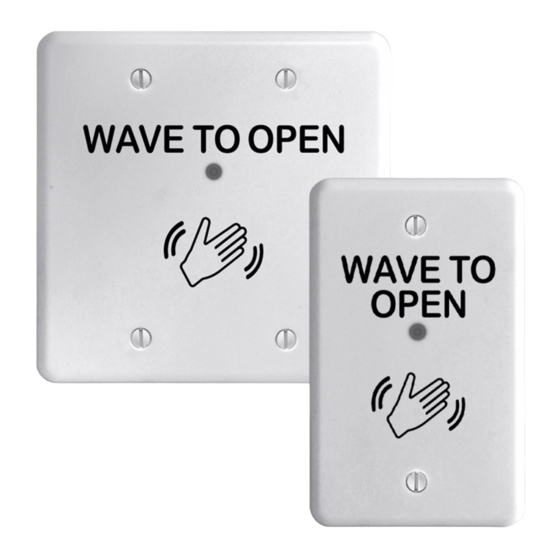
Microwave
motion sensor
•
Faceplate screws
•
Adapter ring
Specifications
ELECTRICAL
OUTPUT
Relay contact rating (max voltage)
Relay contact rating (max current)
Max switching power
DETECTION RANGE
DETECTION MODE
OUTPUT HOLD TIME
OPERATING TEMPERATURE
IMMUNITY
WEIGHT
REGULATORY
Precautions
1.
SHUT OFF power to header before attempting any wiring procedures.
2.
MAINTAIN a clean and safe environment when working in public areas.
3.
Constantly BE AWARE of pedestrian traffic around the door area.
4.
Always
STOP pedestrian traffic through the doorway when performing tests that may
result in unexpected reactions by the door.
5.
OBSERVE
proper protocols for circuit board handling to protect the unit from
electrostatic discharge.
6.
Before handling any board, ENSURE dissipation of any bodily charge.
7.
CHECK placement of all wiring before powering to ensure that moving door parts do
not catch wires and cause damage to equipment.
8.
ENSURE compliance with all applicable safety standards (i.e., ANSI A156.10/A156.19)
upon completion of installation.
1
•
Faceplate
•
Mounting ring
INPUT 12 to 24 VAC ±10%
12 to 24 VDC +30%/-10%
50 to 60 Hz
<1.5W
Relay with switch-over contact (voltage free)
60 VDC/125 VAC
1A (resistive)
30W DC / 60 VAC
4" to 24" (10cm to 60cm)(adjustable)
Motion (bidirectional)
0.5-30 seconds
-4 °F to +131 °F (-20 °C to +55 °C)
Immune to electrical and radio frequency interference
0.34 lbs (0.15 kg)
Electromagnetic compatibility (EMC) according to
2004/108/EC FCC: G9B-21016 IC: 4680A-21016
•
Weather-resistant
gasket
•
Instructions
500-23710_1
Advertisement
Table of Contents

Related Manuals for Assa Abloy Securitron WSS


Summary of Contents for Assa Abloy Securitron WSS
- Page 1 Package Contents • • • Microwave Faceplate Weather-resistant motion sensor gasket • • • Faceplate screws Mounting ring Instructions • Adapter ring Specifications ELECTRICAL INPUT 12 to 24 VAC ±10% 12 to 24 VDC +30%/-10% 50 to 60 Hz <1.5W OUTPUT Relay with switch-over contact (voltage free) 60 VDC/125 VAC...
- Page 2 DO NOT ATTEMPT any repair of the sensor. 10. Unauthorized disassembly or repair: • May jeopardize personal safety and may cause exposure to the risk of electrical shock. Will void the product warranty. • Installation / Wiring / Setup Installation MOUNT the WSS using the included mounting ring or in a standard plastic or metal electrical gang box, as applicable, and depending on the type of door installation.
- Page 3 NOTE: Use either green (N.O.) or yellow (N.C.) wire, not both. Refer to the door control manual to determine which must be used. Setup NOTE: Four adjustments can be made to the sensor. Sensitivity potentiometer: adjust detection field from 4 to 24 inches (rotate clockwise to increase) Factory default: 4 inches (fully CCW) Hold time potentiometer: adjust relay hold time...
- Page 4 2. Wrong connection/Output mode. CHECK wiring and relay connection and switch output mode to Timer. PROBLEM: The door remains open after detection/activation. CAUSE/ACTION: 1. Wrong output mode. SWITCH the output mode to Timer Mode. 2. Wrong connection. CHECK wiring and relay connection. FCC Approval This device complies with Part 15 of the FCC Rules and with RSS-210 of Industry Canada.
Need help?
Do you have a question about the Securitron WSS and is the answer not in the manual?
Questions and answers