Table of Contents
Advertisement
OPERATOR'S MAN U AL
HDS 2.5/20 P Cage / SGP-302017
HDS 2.7/25 P Cage / SGP-302517
HDS 2.6/30 P Cage / SGP-303037
HDS 3.5/30 P Cage / SGP-353037
HDS 3.5/30 PE Cage / SGP-353037E
HDS 3.5/35 PE Cage / SGP-403537E
To locate your local Kärcher Shark Commercial Pressure Washer Dealer nearest you,
visit www.karchercommercial.com or www.karchershark.com
MODEL #
ORDER #
1.575-554.0
1.575-555.0
1.575-550.0
1.575-551.0
1.575-552.0
1.575-553.0
9.800-079.0
R
Advertisement
Table of Contents

Related Manuals for Kärcher HDS 2.5/20 P Cage


Summary of Contents for Kärcher HDS 2.5/20 P Cage
- Page 1 OPERATOR’S MAN U AL MODEL # ORDER # HDS 2.5/20 P Cage / SGP-302017 1.575-554.0 HDS 2.7/25 P Cage / SGP-302517 1.575-555.0 HDS 2.6/30 P Cage / SGP-303037 1.575-550.0 HDS 3.5/30 P Cage / SGP-353037 1.575-551.0 HDS 3.5/30 PE Cage / SGP-353037E 1.575-552.0...
-
Page 2: Table Of Contents
CONTENTS Introduction & Important Safety Instructions Component Identifi cation Assembly Instructions Operating Instructions Detergents and Cleaning Tips Shut-Down and Clean Up Storage Maintenance 12-14 Troubleshooting 15-17 Maintenance & Oil Change Charts Exploded View - 554.0, 555.0 Exploded View - 550.0, 551.0, 552.0, 553.0 20-21 Exploded View Parts Lists 22-25... -
Page 3: Introduction & Important Safety Instructions
INTRODUCTION & IMPORTANT SAFETY INFORMATION Thank you for purchasing this Pressure Washer. WARNING: This machine exceeds WARNING 85 db appropriate ear protection We reserve the right to make changes at any time must be worn. without incurring any obligation. Owner/User Responsibility: The owner and/or user must have an understanding of the manufacturer’s operating instructions and warnings before using this pressure washer. - Page 4 IMPORTANT SAFETY INFORMATION Gasoline engines on mobile or portable equipment WARNING: Grip cleaning wand WARNING shall be refueled: securely with both hands before starting. Failure to do this could a. outdoors; result in injury from a whipping b. with the engine on the equipment stopped; wand.
- Page 5 IMPORTANT SAFETY INFORMATION WARNING: Be extremely careful WARNING when using a ladder, scaffolding or any other relatively unstable location. The cleaning area should have adequate slopes and drainage to reduce the pos- sibility of a fall due to slippery RISK OF INJURY surfaces.
-
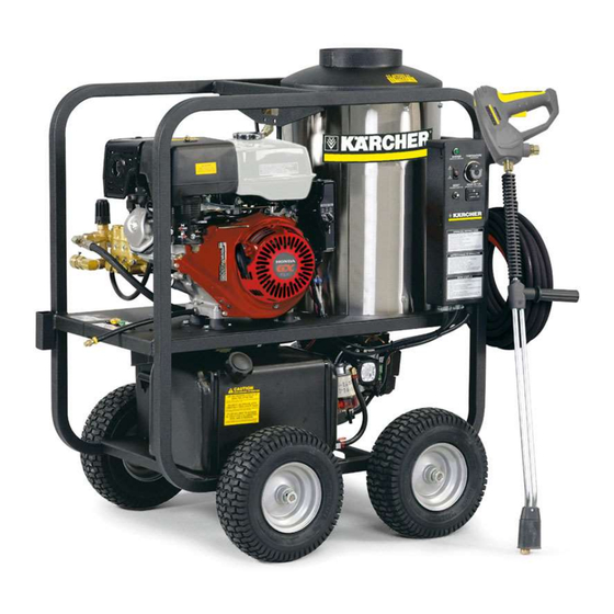
Page 6: Component Identification
COMPONENT IDENTIFICATION Gasoline Tank Discharge Detergent Nipple Injector Pressure Switch Unloader Collar Quick Water Supply Coupler Hose (not included) Pump Spray Battery Box Wand Coupler Nozzle Quick Swivel Coupler Connector Brass Variable Pressure Soap Control wand Nozzle Control Wand Handle High Pressure Hose Trigger... -
Page 7: Assembly Instructions
ASSEMBLY INSTRUCTIONS Pressure Spray Soap Nozzle Nozzle Wand Coupler Safety Wand Latch Coupler Wand Collar High Pressure Hose STEP 1: Attach the high STEP 2: Pull the spring-load ed col lar STEP 3: Release the coupler col lar pres sure hose to the spray of the wand coupler back to in sert your and push the nozzle until the collar gun using teflon tape on hose... -
Page 8: Operating Instructions
OPERATING INSTRUCTIONS Oil Dipstick Tank STEP 1: Check engine oil level. Oil level should be level with the bottom STEP 2: Fill gas tank with un lead ed of the oil filler neck. Be sure the ma chine is level when checking the oil gasoline. - Page 9 OPERATING INSTRUCTIONS Throttle STEP 7: Turn the engine to "Run" position. STEP 8: Pull the starter grip. If the engine fails to start after 2 pulls, squeeze the trigger gun to release pres sure and repeat step. Return start er gently. After the en gine warms up enough to run smoothly, move choke to run position and throt tle to fast position.
-
Page 10: Detergents And Cleaning Tips
DETERGENTS AND CLEANING TIPS THERMAL PUMP PROTECTION WARNING: Some de ter gents WARNING may be harm ful if in haled or in - If you run the engine on your pres sure wash er for 3-5 gest ed, caus ing severe nau sea, min utes with out pressing the trig ger on the spray gun, fainting or poi son ing. -
Page 11: Shut-Down And Clean Up
SHUTTING DOWN AND CLEAN-UP On-Off Switch STEP 1: Re move detergent suc tion STEP 2: Turn off the engine. STEP 3: Tur n off water tube from container and insert into supply. 1 gallon of fresh water. Turn vari able pressure wand handle for low pres- sure or connect the black de ter gent noz zle. -
Page 12: Maintenance
MAINTENANCE During winter months, when tem per a tures drop below PREVENTATIVE MAINTENANCE 32°F, protecting your machine against freezing is nec- es sary. Store the machine in a heated room. If this is not 1. Check to see that the water pump is properly lu bri - pos si ble then mix a 50/50 solution of anti-freeze/water cat ed. - Page 13 MAINTENANCE Fuel: Burner Nozzle: Use clean fuel oil that is not contaminated with water Keep the tip free of surface deposits by wiping it with a and debris. Replace fuel filter and drain tank every 100 clean, solvent-saturated cloth, being careful not to plug hours of operation.
- Page 14 MAINTENANCE as can be obtained, then repeat the above procedure 4. Clean, repair and replace the coil by reversing the on the air band setting. above steps. Coil Reinstallation: Fuel Pressure Adjustment: To adjust fuel pressure, turn the adjusting screw clock- Reinstall by reversing the above steps 4 through 1.
-
Page 15: Troubleshooting
TROUBLESHOOTING PROBLEM POSSIBLE CAUSE SOLUTION LOW OPERATING Water supply is insufficient Use larger supply hose; clean filter at water inlet. PRESSURE Spray nozzle is old, worn or Match the nozzle number to the machine incorrect and/or replace with new nozzle. Belt slips Tighten or replace belt;... - Page 16 TROUBLESHOOTING PROBLEM POSSIBLE CAUSE SOLUTION BURNER WILL Burner nozzle is clogged Clean as required. NOT LIGHT Thermostat has malfunctioned Test and replace if needed. (continued from previous page) Fuel solenoid has malfunctioned Test and replace if needed. MACHINE Fuel is improper or water is in fuel Drain tank and replace contaminated fuel.
- Page 17 TROUBLESHOOTING PROBLEM POSSIBLE CAUSE SOLUTION DETERGENT NOT Air is leaking Tighten all clamps. Check detergent lines for holes. DRAWING Injector head may be blocked, Clean and make sure ball and spring behind dirty or damaged detergent hose barb or injector body are working properly.
-
Page 18: Maintenance & Oil Change Charts
MAINTENANCE CHARTS PREVENTATIVE MAINTENANCE This pressure washer was produced with the best available materials and quality craftsmanship. However, you as the owner have certain responsibilities for the correct care of the equipment. Attention to regular preventative main te nance procedures will assist in preserving the performance of your equipment. Contact your dealer for main te nance. -
Page 19: Exploded View - 554.0, 555.0
EXPLODED VIEW - 554.0, 555.0 MODELS Reversed View Reversed View of labels of label s or tion s che s Eq tain atio 7-01 t con tion rt Fir . The 8.91 n Sta s or s.” a to t Ca “Th lifo s Tha... -
Page 20: Exploded View - 550.0, 551.0, 552.0, 553.0
EXPLODED VIEW - 550.0, 551.0, 552.0, 553.0 MODELS Reversed View of labels Detail See Control Box Illus. Reversed View of Component For Brake Honda Electric Detail See Start Only View A-A (Enlarged) pg. 21 9.800-079.0 • Rev. 04/10... - Page 21 EXPLODED VIEW - 550.0, 551.0, 552.0, 553.0 MODELS Steam Option Steam Option 53, 69 Electric Start Model Only View A-A (Enlarged) 9.800-079.0 • Rev. 04/10...
- Page 22 EXPLODED VIEWS PARTS LIST ITEM PART NO. DESCRIPTION 9.803-029.0 Tank Head Assembly, 16" Diameter x 8" Stack 9.800-006.0 Label, Hot/Caliente w/Arrows Warning 9.802-825.0 Clip, Retaining, U-Type 9.803-030.0 Retainer, Burner Insulation 9.803-134.0 Coil, Dura, 14.5" Dia., Sch 80 (550.0, 551.0, 552.0, 553.0) 9.803-095.0 Coil Assembly (554.0, 555.0) 8.915-908.0...
- Page 23 EXPLODED VIEWS PARTS LIST ITEM PART NO. DESCRIPTION 9.802-254.0 Hose, 1/4", Push-On, Fuel Line (Steam Option) 14 in. 9.802-075.0 Box, Battery, M-100 (552.0, 553.0) ▲ Plate, Battery Box, Large, PolyPro (552.0, 553.0) 9.802-076.0 9.802-081.0 Tank, Fuel, 6 Gallon 9.802-089.0 Cap, Fuel Tank, Plastic H60-AV 9.802-832.0 Bolt, 5/16"...
-
Page 24: Exploded View Parts Lists
EXPLODED VIEW PARTS LIST ITEM PART NO. DESCRIPTION 9.802-816.0 Washer, 7/16" Lock (551.0, 552.0, 553.0) 9.802-958.0 Key, 0.185 SQR x 1.75" (554.0, 555.0) 9.802-959.0 Key, 0.247 SQR x 2.125 (550.0, 551.0, 552.0, 553.0) 9.803-108.0 Retainer Ring, Insulation 9.802-773.0 Nut, 1/4"-20, ESNA 9.802-996.0 Bracket, Brake Pad, Black 9.800-094.0... - Page 25 EXPLODED VIEW PARTS LIST ITEM PART NO. DESCRIPTION 9.803-092.0 Fuel Tank Strap, Long 9.802-459.0 Switch, MV60 Flow (Steam Option) 9.802-104.0 Bushing, 3/4" Snap (554.0, 555.0) 9.802-254.0 Hose, 1/4" Push-On (554.0, 555.0) 7" (550.0, 551.0, 552.0, 553.0) 11" 9.802-039.0 Elbow, 1/2" JIC x 3/8", 90° (Steam Option) 9.802-143.0 Elbow, 1/4"...
-
Page 26: Control Panel - 554.0, 555.0 & Parts List
CONTROL PANEL EXPLODED VIEW - 554.0, 555.0 MODELS 5,25 Reversed View 554.0, 555.0 CONTROL PANEL PARTS LIST ITEM PART NO. DESCRIPTION 9.802-528.0 Capacitor 9.802-531.0 Regulator, Voltage, 15 Volt 9.803-036.0 Box, Electrical 9.803-121.0 Assembly, Cover, Electrical Box 8.750-094.0 Thermostat, Adjustable, 302°F 9.802-456.0 Light, Indicator, Green 12 Volt 9.802-453.0... - Page 27 554.0, 555.0 CONTROL PANEL PARTS LIST ITEM PART NO. DESCRIPTION 9.802-206.0 Clamp, Hose 9.802-791.0 Nut, Cage, 10/32" x 16 Gauge 9.800-098.0 Label, Control Panel 9.802-802.0 Washer, 1/4", Flat, SAE 9.802-695.0 Nut, 10/32" Keps 9.802-771.0 Screw, 10/32" x 3/4" 9.802-759.0 Screw, 10/32" x 1/2" 9.803-048.0 Cap, Capacitor, 1.37 x 1.50 x .060 Blk, w/o Hole 9.803-840.0...
-
Page 28: Control Panel - 550.0, 551.0, 552.0, 553.0 & Parts List
CONTROL PANEL - 550.0, 551.0, 552.0, 553.0 1, 23 550.0, 551.0, 552.0, 553.0 CONTROL PANEL PARTS LIST ITEM PART NO. DESCRIPTION 8.750-094.0 Thermostat, Adjustable, 302°F 9.803-035.0 Cover, Electric Box, Black 9.802-759.0 Screw, 10/32" x 1/2" BHSOC, Black 9.802-485.0 Breaker, 1658-G41-02-P10-25A 9.802-525.0 Locknut, 1/2"... - Page 29 550.0, 551.0, 552.0, 553.0 CONTROL PANEL PARTS LIST ITEM PART NO. DESCRIPTION 9.802-453.0 Switch, Curvette RA901VB-B-1-V, Carling 9.802-519.0 Strain Relief, 1/2" Metal, Two Screw 9.802-514.0 Strain Relief, Small 9.803-071.0 Box, Electric, Black 9.802-788.0 Nut, 5/16" Whiz Loc Flange 9.802-530.0 Rectifi er, Bridge (552.0, 553.0) 9.802-470.0 Relay, P &...
-
Page 30: Hose & Spray Gun Assembly & Parts List
HOSE & SPRAY GUN ASSEMBLY Pressure Nozzle HOSE & SPRAY GUN PARTS LIST ITEM PART NO. DESCRIPTION 9.802-166.0 Coupler, 3/8" Female ▲ Quick Coupler O-Ring LG 9.802-100.0 8.739-125.0 Hose, 3/8" x 50', 1 Wire Tuff Flex (All Models Except 553.0) 8.739-203.0 Hose, 3/8"... -
Page 31: Downstream Injector Assembly
DOWNSTREAM INJECTOR ASSEMBLY DOWNSTREAM INJECTOR PARTS LIST ITEM PART NO. DESCRIPTION 9.802-216.0 Injector, Detergent, Non-Adjusting #3 9.802-215.0 Injector, Detergent, Non-Adjusting #2 6.390-126.0 Clamp, Hose, UNI .46 - .54 9.802-251.0 Tube, 1/4" x 1/2", Clear Vinyl 6 ft. 9.802-160.0 Strainer, 1/4", Hose Barb 9.800-079.0 •... -
Page 32: Hose Reel Option
HOSE REEL OPTION HOSE REEL PARTS LIST ITEM PART NO. DESCRIPTION 9.802-166.0 Coupler, 3/8", Female, Brass 9.802-244.0 Hose, 3/8", 2 Wire Pressure Loop 9.802-269.0 Hose Reel, 100' Non-Pivot E-ZEE w/Pin Lock 9.802-767.0 Screw, 3/" x 3/4" HH NC, Whiz Loc 9.802-781.0 Nut, 3/8"... -
Page 33: Uu1 Unloader Exploded View And Parts List
UU1 UNLOADER EXPLODED VIEW 9.175-018.0 UU1 3500PSI, UNIVERSAL UNLOADER (SPARE) UU1 UNLOADER EXPLODED VIEW PARTS LIST ITEM PART # DESCRIPTION KIT QTY ITEM PART # DESCRIPTION KIT QTY 8.749-792.0 Piston housing 9.149-006.0 Sliding connector guide Piston O-ring backup 6X 1.45X 1.68 Piston O-ring back up Conical seal 8.749-796.0 Main block... -
Page 34: Ks.2 Pump Exploded View And Parts List
KS.2 PUMP EXPLODED VIEW 9.841-643.0 KS3040G.2 9.802-349.0 KS3540G.2 9.802-350.0 KS4040G.2 9.803-409.0 KS5030G.2 TORQUE SPECS Item # Ft.-lbs KS.2 PUMP EXPLODED VIEW PARTS LIST ITEM PART NO. DESCRIPTION ITEM PART NO. DESCRIPTION 8.717-129.0 Crankcase 9.802-939.0 Hexagonal Screw 9.803-210.0 Washer 9.803-196.0 Plunger Guide See Kit Below Plunger Oil Seal 9.803-184.0 Closed Bearing Housing... - Page 35 KS.2 PUMP EXPLODED VIEW PARTS LIST (CONT.) ITEM PART NO. DESCRIPTION 9.803-216.0 Washer 9.803-217.0 Spring Washer 9.803-142.0 Crankshaft Seal 47* See Kit Below Plunger Nut 48* See Kit Below Washer, Copper, 9.2 x 13.5 49* See Kit Below Plunger, 15mm 50* See Kit Below Copper Spacer 51* See Kit Below O-Ring Ø1.78x5.28 52* See Kit Below Tefl...
-
Page 36: Kg.2 Pump Exploded View And Parts List
KG.2 PUMP EXPLODED VIEW 9.803-819.0 KG3035G1 9.803-820.0 KG3535G1 9.803-821.0 KG4030G1 TORQUE SPECS Item # Ft.-lbs KG.2 PUMP EXPLODED VIEW PARTS LIST ITEM PART NO. DESCRIPTION ITEM PART NO. DESCRIPTION 9.803-938.0 Crankcase 9.803-952.0 Manifold Stud Bolt See Kit Below Plunger Oil Seal 9.802-884.0 Washer See Kit Below O-Ring Ø1.78 x 31.47... - Page 37 KG.2 PUMP EXPLODED VIEW PARTS LIST (CONT) ITEM PART NO. DESCRIPTION 8.933-020.0 Flange Screw 9.803-142.0 Crankshaft Seal 47* See Kit Below Plunger Nut 48* See Kit Below Copper Washer 49* See Kit Below Plunger, 15mm 50* See Kit Below Copper Spacer 51* See Kit Below O-Ring Ø1.78x5.28 52* See Kit Below Tefl...
-
Page 38: Burner Specifi Cations
SPECIFICATIONS BECKETT BURNER SPECIFICATIONS Fuel Pump/ Fuel Pump/ Model # Burner Assy # Fuel Nozzle Transformer Burner Motor Solenoid Cord Solenoid Coil Electrode 1.575-554.0 9.802-554.0 9.802-585.0 9.802-663.0 9.802-638.0 9.802-562.0 9.802-639.0 9.802-670.0 1.575.555.0 9.802-554.0 9.802-585.0 9.802-663.0 9.802-638.0 9.802-562.0 9.802-639.0 9.802-670.0 1.575-550.0 9.802-560.0 9.802-582.0 9.802-663.0... - Page 39 LIMITED NEW PRODUCT Phone: 360-833-1600 WARRANTY—COMMERCIAL Fax: 800-248-8409 www.karchercommercial.com PRESSURE WASHERS WHAT THIS WARRANTY COVERS All Kärcher commercial pressure washers are warranted by Kärcher to the original purchaser to be free from defects in materials and workmanship under normal use, for the periods specified below. This Limited Warranty, subject to the exclusions shown below, is calculated from the date of the original purchase, and applies to the original components only.
- Page 40 www.karchercommercial.com www.karchershark.com Form # 9.800-079.0 • Revised 04/10 • Printed in U.S.A. or Mexico...
Need help?
Do you have a question about the HDS 2.5/20 P Cage and is the answer not in the manual?
Questions and answers