Table of Contents
Advertisement
Quick Links
! $Instruments
길 우 트 레 이 딩
서울특별시 영등포구 선유로33길 15
703호(양평동3가, 에이스테크노타워)<150-962>
02)2636-0009 팩스02)2636-4753
www.gilwoo.co.kr giltron@naver.com
www.gilwooshop.co.kr
©2005-2013 Applent Instruments
English
Revision A2
FIRMWARE REVISIONS
This manual applies directly to instruments that
have the firmware Rev.C1.x
Manual Print History
The print history shown below lists the printing dates of all Revisions and Addenda
created for this manual. The Revision Level letter increases alphabetically as the manual
undergoes subsequent updates. Addenda, which are released between Revisions, contain
important change information that the user should incorporate immediately into the
manual. Addenda are numbered sequentially. When a new Revision is created, all
Addenda associated with the previous Revision of the manual are incorporated into the
new Revision of the manual. Each new Revision includes a revised copy of this print
history page.
Revision A January, 2013
[
AT5110
Multi‐Channel Resistance Meter
User's Guide
]
Advertisement
Table of Contents

Related Manuals for Applent Instruments AT5110


Summary of Contents for Applent Instruments AT5110
- Page 1 ! $Instruments 길 우 트 레 이 딩 서울특별시 영등포구 선유로33길 15 703호(양평동3가, 에이스테크노타워)<150-962> 02)2636-0009 팩스02)2636-4753 www.gilwoo.co.kr giltron@naver.com www.gilwooshop.co.kr ©2005-2013 Applent Instruments English Revision A2 FIRMWARE REVISIONS This manual applies directly to instruments that have the firmware Rev.C1.x Manual Print History The print history shown below lists the printing dates of all Revisions and Addenda created for this manual.
-
Page 2: Certification, Limited Warranty, & Limitation Of Liability
CERTIFICATION, LIMITED WARRANTY, & LIMITATION OF LIABILITY Applent Instruments, Inc. (shortened form Applent)certifies that this product met its published specifications at the time of shipment from the factory. Applent further certifies that its calibration measurements are traceable to the People’s Republic of China National Institute of Standards and Technology, to the extent allowed by the Institution’s calibration facility or by the calibration facilities of other International Standards Organization... -
Page 3: Table Of Contents
Contents Contents CERTIFICATION, LIMITED WARRANTY, & LIMITATION OF LIABILITY ............. 2 Contents ..................................3 Figure Contents................................5 Table Contents ................................6 1. Unpacking and Preparation ..........................7 1.1 Incoming Inspection .......................... 7 1.2 Setting up Fuse ..........................7 1.3 Environmental Requirements ......................7 1.4 ... - Page 4 AT5110 User's Guide 6.1.3 Beep Feature ..........................26 6.1.4 RS-232 Baud Rate [BAUD] ....................26 6.1.5 RS-232 Shake Hand [SHAKE HAND] ................... 26 6.1.6 RS-232 Result Send Mode [RESULT SEND] ................. 27 6.1.7 Data format and EOC mode [DATA/EOC] ................27 ...
- Page 5 Contents Figure Contents Figure 1-1 How to remove the handle ......................9 Figure 3-1 Front panel ..........................12 Figure 3-2 Real Panel ..........................12 Figure 3-3 Test Terminal of Each Channel ....................13 Figure 4-1 <MEAS DISPLAY> Page ......................15 Figure 5-1 ...
- Page 6 AT5110 User's Guide Table Contents Table 3-1 Front panel description ......................12 Table 3-2 Real panel description ......................13 Table 5-1 Range Mode ........................... 18 Table 5-2 Effective measurement range ....................18 Table 7-1 Description of Handler Interface Signals ................. 29 ...
-
Page 7: Unpacking And Preparation
Unpacking and Preparation Unpacking and Preparation This chapter describes how to set up and start the AT5110 Multi-Channel Resistance Meter. Incoming Inspection Power Requirements Setting up the Fuse How to Remove the Handle Environmental Requirements Cleaning... -
Page 8: Cleaning
Altitude: 0 to 2,000m Vibration: Max. 0.5 G, 5 Hz to 500 Hz Cleaning To prevent electrical shock, disconnect the AT5110 power cable from the receptacle before cleaning. Use a dry cloth or a cloth slightly dipped in water to clean the casing. - Page 9 Unpacking and Preparation Figure 1‐1 How to remove the handle 1 Retracted 3 Carrying Position 2 Extended Remove Handle(Lift the handle perpendicular to the unit while pulling it in the direction of 1.)...
-
Page 10: Overview
With its built-in comparator, the AT5110 can output comparison/decision results for sorting components into a maximum of ten channels. Furthermore, by using the handler interface, the AT5110 can be easily combined with a component handler, and a system controller to fully automate component testing, sorting, and quality-control data processing. -
Page 11: Main Functions
Overview Main Functions 2.3.1 Correction Function SHORT correction: Eliminates measurement errors brought about by stray parasitic impedance in the test fixtures. 2.3.2 Comparator Function (Sorting) The primary parameter can be sorted into ten NG Bin: CH1-CH10 The sequential mode or tolerance mode can be selected as the sorting mode. Limit Setup Absolute value, deviation value, and % deviation value can be used for setup. -
Page 12: Startup
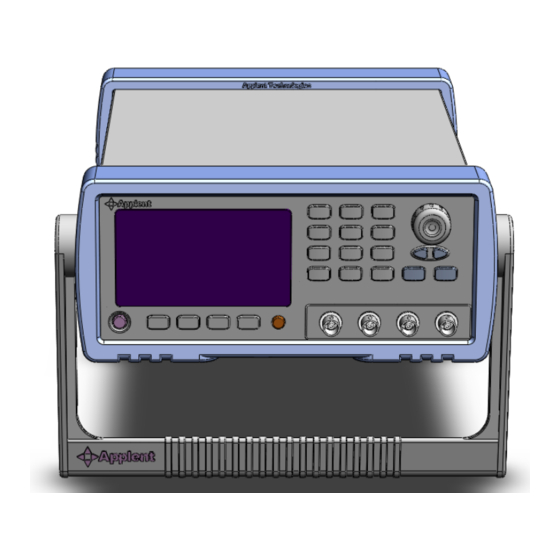
AT5110 User's Guide Startup This chapter describes names and functions of the front panel, rear panel, and screen display and provides the basic procedures for operating AT5110. Front panel summary Rear panel summary Power On/Off Connect to Device under Test Front panel Figure 3‐1... -
Page 13: Power On/Off
Power ON. Power OFF. Warm‐up Time AT5110 is ready to be used as soon as the power-up sequence has completed. However, to achieve the accuracy rating, warm up the instrument for 30 minutes. Connect to Device under Test (DUT) The test terminals of all channels are on the real panel. - Page 14 AT5110 User's Guide SENSE+ SENSE- DRIVE+ DRIVE- Warning: No putting current source, voltage source directly access to test side. Energy storage device access to testing after discharging.
-
Page 15: Meas] Key
AT5110 performs one cycle of measurement each time you press the [Trig] key. AT5110 performs one cycle of measurement each time a rising pulse is input to the handler external trigger input pin on the rear panel. Please refer to the Handler section. -
Page 16: 01-10] Channel Setup
AT5110 User's Guide External Trigger Mode BUS Trigger Mode 4.1.2 [01‐10] Channel Setup SCPI Command: FUNCtion:SCAN {ON,OFF,<channel no>} Each channel can be turned ON/OFF or fixed to single channel measurement. Procedure for setting the channel [01]-[10] Step 1. Press the [Meas] key Step 2. -
Page 17: Setup] Key
NOTE: *1. These two settings can be set in <MEAS DISPLAY> page. Please refer Sector 4.1 <MEAS DISPLAY> Page to set. 5.1.1 Trigger Mode [TRIG] SCPI Command: TRIGger:SOURce {INT,MAN,EXT,BUS} AT5110 supports four trigger modes: INT (internal), EXT (external), MAN (manual) and BUS (RS-232). -
Page 18: Range [Range]
AT5110 performs one cycle of measurement each time you press the [Trig] key. AT5110 performs one cycle of measurement each time a rising pulse is input to the handler external trigger input pin on the rear panel. Please refer to the Handler section. -
Page 19: Measurement Speed [Rate]
DECR - Decrements the range in the HOLD mode 5.1.3 Measurement Speed [RATE] SCPI Command: FUNCtion:RATE {SLOW,MED,FAST,ULTRA} SLOW, MED, FAST, ULTRA can be selected for AT5110. SLOW mode will result in more stable and accurate measurement result. When in Range-Hold mode: Slow: 3.4s/10-Channel... -
Page 20: Scan] Mode
Increase the channel number DEC - Decrease the channel number 5.1.6 Turn Temperature Compensation ON/OFF SCPI Command: FUNCtion:TC {ON,OFF,1,0} The AT5110 built in Temperature Compensation Interface. The Temperature Compensation Formula is: Where, T0: Reference Temperature T: Current Room Temperature α : Temperature coefficient of reference temperature (%) -
Page 21: Reference Temperature [Refer Temp]
Please make sure the test clips short-circuit is like the following way: Step 5. Press [OK] soft key. The AT5110 measures short resistance at the all ranges. During the measurement, an “SHORT measurement in progress” dialog message is shown on the display. -
Page 22: Turn The Comparator On/Off [Comp]
AT5110’s built-in comparator can sort each channel’s DUTs into their respective NG bin (CH1 through CH10 and NG (All Channel). To take full advantage of the comparator, AT5110 is equipped with a handler interface for use in conjunction with the comparator. All CH1~CH10 NG signal can output to yours PLC via the handler interface. -
Page 23: Nominal Value For Tolerance Mode
[Setup] Key Sequential mode [SEQ] In sequential mode, the comparison limit values are based on the absolute value of the measurement. When you configure these limit values, you have to first define the minimum value and then the maximum value. Tolerance mode Tolerance mode includes deviation percentage (%) or absolute (). -
Page 24: System Configurations
Figure 6‐1 <SYSTEM CONFIG> Page 6.1.1 Setting the system date and time AT5110 features a built-in 24-hour clock. To change the date Step 1. Press the [Meas] or [Setup] key Step 2. Press the [SYSTEM] bottom soft key. Step 3. Use the cursor key to select date field Step 4. -
Page 25: Account Setting
Decreases the second in steps of 1. 6.1.2 Account Setting The AT5110 has two accounts, administrator and user. Administrator: All functions can be configured by administrator except <SYSTEM SERVICE> page. User: All functions can be configured by user except < SYSTEM SERVICE> page and <FILE>... -
Page 26: Beep Feature
Beep while the comparator sorting result is NG 6.1.4 RS‐232 Baud Rate [BAUD] Before you can control the AT5110 by issuing RS-232 commands from built-in RS-232 controller connected via its DB-9 connector, you have to configure the RS-232 baud rate. The AT5110’s built-in RS-232 interface uses the SCPI language. -
Page 27: Rs-232 Result Send Mode [Result Send]
Function FETCH Acquire the test result by sending “FETCH?” command only. AUTO AT5110 return the result every EOM 6.1.7 Data format and EOC mode [DATA/EOC] SCPI Command: SYSTem:DATAmode {ALL,ONE} When the [RESULT SEND] field is set to [AUTO], the data format will return to host depended on this field. -
Page 28: System Info> Page
AT5110 User's Guide <SYSTEM INFO> Page When press the [Meas] or [Setup] key followed by [SYSTEM] bottom soft key, and press [SYSTEM INFO] soft key, the <SYSTEM INFO> page appears. There are no configurable options in the <SYSTEM INFO> page. Figure 6‐2 <SYSTEM INFO> Page... -
Page 29: Handler Interface
In addition, the instrument accepts input of external trigger. You can use these signals to easily integrate the AT5110 with a component handler or system controller. This means that you can fully automate such tasks as component inspection, component sorting, and processing of quality management data for higher manufacturing efficiency. -
Page 30: Power Rating
AT5110 User's Guide Internal GND 27-28 Internal GND Power Common signal of internal VCC. External GND 29-30 External GND Power Common signal for external DC current External VCC External VCC (3.3V~35V) 33-34 External VCC Power Supplies voltage for DC isolation input... - Page 31 Handler Interface JP204 R24 3 EXVCC TRIG U221 P521 JP205 Figure 7‐3 Typical Circuit Diagram of Handler Interface Output signals. EXT.DCV 4.99k OUTPUT GN D...
-
Page 32: Remote Control
AT5110 User's Guide Remote Control This chapter provides the following information to remotely control the AT5110 via the RS-232C or USB interface. About RS-232C About USB Interface Select Baud Rate. About SCPI AT5110 can use the RS-232 interface or USB interface to communicate with the computer to complete all the instrument functions. -
Page 33: About Usb-Serial Interface (Option)
Remote Control About USB‐Serial Interface (Option) The USB-Serial Interface allows you to connect AT5110 to a USB port on your PC. NOTE: Please install the USB-Serial driver before using USB-Serial Interface. The Applent USB-Serial interface model is ATN2. Figure 8‐2 USB‐Serial Interface ATN2 To Select Baud Rate Before you can control the AT5110 by issuing RS-232 commands from built-in RS-232 controller connected via its DB-9 connector, you have to configure the RS-232 baud rate. - Page 34 AT5110 User's Guide RS-232 interfaces. NOTE: AT5110 ONLY supports the SCPI Language.
-
Page 35: Command Reference
The common commands are defined in IEEE std. 488.2-1987, and these commands are common for all devices. The SCPI commands are used to control all of the AT5110's functions. The SCPI commands are tree structured three levels deep. The highest level commands are called the subsystem commands in this manual. - Page 36 AT5110 User's Guide ROOT COMmand1 COMmand2 COMmand3 COMmand4 COMmand5 Example: ROOT:COMmand3:COMmand5 ppp ROOT Subsystem Command COMmand3 Level 2 COMmand5 Level 3 Parameter The basic rules of the command tree are as follows. Letter case (upper and lower) is ignored.
-
Page 37: Header And Parameters
Command Reference The AT5110 accepts the three forms of the same SCPI commands: all upper case, all lower case, and mixed upper and lower case. Header and Parameters The commands consist of a command header and parameters. (See the following.) For example comp:nom 100.0e3... -
Page 38: Display Subsystem
AT5110 User's Guide COMParator Subsystem CORRection Subsystem TRIGger Subsystem ERRor Subsystem Common Command: IDN? DISPlay Subsystem The DISP Subsystem command group sets the display page. Figure 9‐2 DISP Command Tree DISPlay :PAGE {MEASurement, SETUp, COMParator,SYSTem, SYSTEMINFO(SINF)} :LINE <string>... -
Page 39: Function:range
Command Reference measurement range, monitors parameter control. Figure 9‐3 FUNCtion Subsystem Tree FUNCtion :RANGe {Range Number,max,min} :MODE {AUTO,HOLD,NOMinal} :RATE {SLOW,MED,FAST,ULTRA} : COEFficient <float> :REFEr <float> :SCAN {<channel number>,on,off} 9.7.1 FUNCtion:RANGe The FUNCtion:RANGe command sets the range. Command Syntax FUNC:RANGe <0-7,MIN,MAX> Parameter Where, <0-7,MIN, MAX> is: 0-7, The range number MIN, =Range 0 MAX, =Range 7... -
Page 40: Function:tc
AT5110 User's Guide 9.7.4 FUNCtion:TC The FUNC:TC command turns the temperature compensation function ON/OFF. Command Syntax FUNCtion:TC {on,off,1,0} Example SEND> FUNC:TC ON <NL> Query Syntax FUNC:TC? Query Response {ON,OFF} 9.7.5 FUNCtion:TC: COEFficient The FUNC:TC:COEF command sets the material coefficient. Command Syntax FUNCtion:TC:COEFficient {float} Example SEND>... -
Page 41: Comparator:state
Command Reference 9.8.1 COMParator:STATe The COMParator:STATe command sets the comparator function to OFF or the total number of bins.. Command Syntax COMParator[:STATe] {ON,OFF,1,0} Example SEND> COMP:STAT ON <NL> SEND> COMP:STAT 1 <NL> Query Syntax COMParator:STATe? Query Response {on,off} 9.8.2 COMParator:MODE The :COMParator:MODE command sets the limit mode of the comparator function. -
Page 42: Trigger Subsystem
AT5110 User's Guide Parameter Where,<n>,<low limit>,<high limit> is: 1~10 Channel number low limit <float> low limit value high limit <float> high limit value Example SEND> COMP:CH 1,1,2 <NL> SEND> COMP:CH 2,-10,10 <NL> Query Syntax COMParator:CH? <1~10> Parameter Where,<1~10> is: Channel Number Query Response <float:low limit>,<float:high limit>... -
Page 43: Fetch Subsystem
Command Reference Execute Trigger command but return the test result. Command Syntax *TRG Query Response <primary value>,<comparator result> Example SEND> TRG RET> +5.566785e-01,BIN01 RET> +1.00000E+20,BIN00 //OPEN or OVERLOAD Note This command can be used ONLY in BUS trigger mode. 9.10 FETCh Subsystem The FETCh subsystem command group is a sensor-only command which retrieves the measurement data taken by measurement(s) initiated by a trigger, and places the data... -
Page 44: System:datamode
AT5110 User's Guide Query Syntax SYST:SEND? Query Response <FETCH,AUTO > 9.11.2 SYSTem:DATAmode SYST:DATA command sets the RS-232 Result Data Format and EOC Mode.. Command Syntax SYSTem:DATAmode {ALL,ONE} Example SEND> SYST:DATA ONE <NL> Query Syntax SYST:SEND? Query Response <ALL,ONE> 9.12 CORRection Subsystem The CORRection subsystem command group to execute the short-circuit clear zero correction function. -
Page 45: Specification
Specification Specification This chapter describes the specifications and supplemental performance characteristics of the AT5110: Specifications Dimension Accuracy is defined as meeting all of the following conditions. Temperature: 23℃±5℃ Humidity: 65% R.H. Zeroing: Open and Short Correction Warm up time is 30 min or more. -
Page 46: Dimensions
AT5110 User's Guide Programming language: SCPI Environment: Temperature and humidity range: 15℃ 35 , ℃ 80% RH or less Storage temperature and humidity range: 10 ~40 ,10~90% RH ℃ ℃ Power Supply: AC 110V/220V, 48.5Hz-62.5Hz Fuse: 1A Slow-Blow Maximum rated power:...
Need help?
Do you have a question about the AT5110 and is the answer not in the manual?
Questions and answers