Table of Contents
Advertisement
Quick Links
! $Instruments
Applent Instrument, Inc.
3 Floor, No. 61, Baolong International,
Zhonglou District, Changzhou, Jiangsu,
China
[213002]
+86-0519-88805550
Fax:+86-0519-86922220
http://www.applent.com
Sales Email:
sales@applent.com
Tech Email:
tech@applent.com
©2005-2010 Applent Instruments, Inc.
Rev.B
[AT512 PRECISION RESISTANCE METER ]
User's Manual
Advertisement
Table of Contents

Related Manuals for Applent Instruments AT512


Summary of Contents for Applent Instruments AT512
- Page 1 ! $Instruments Applent Instrument, Inc. 3 Floor, No. 61, Baolong International, Zhonglou District, Changzhou, Jiangsu, China [213002] +86-0519-88805550 Fax:+86-0519-86922220 http://www.applent.com Sales Email: sales@applent.com Tech Email: tech@applent.com ©2005-2010 Applent Instruments, Inc. Rev.B [AT512 PRECISION RESISTANCE METER ] User’s Manual...
-
Page 2: Safety Summary
When you notice any of the unusual conditions listed below, immediately terminate operation and disconnect the power cable.Please Contact Applent Instruments Incorporation sales representative for repair of the instrument. If you continue to operate without repairing the instrument, there is a potential fire or shock hazard for the operator. -
Page 3: Certifiaction, Limited & Limitation Of Liability
Unpacking and Inspection CERTIFIACTION, LIMITED & LIMITATION OF LIABILITY Applent Instruments, Inc. (shortened form Applent)certifies that this product met its published specifications at the time of shipment from the factory. Applent further certifies that its calibration measurements are traceable to the People’s Republic of China National Institute of Standards and Technology, to the extent allowed by the... -
Page 4: Table Of Contents
AT512 Precision Resistance Meter Contents Safety Summary ..............................2 Safety Summary ..............................2 CERTIFIACTION, LIMITED & LIMITATION OF LIABILITY ..............3 Contents ................................4 Unpacking and Inspection ..........................5 Packing List ............................5 Power Supply ............................. 5 Setup Fuse ............................5 Operating Environment........................ -
Page 5: Unpacking And Inspection
Kelvin Test Leads ATL501 Test Report Product & Warranty Certification Power Supply Confirm that the power supplied to the AT512 meets the following requirements: Voltage:198-252V AC/110V Frequency:50/60Hz Consumption:15VA WARNING: The ground wire should be earthed to avoid being electric shock. -
Page 6: Operating Environment
Temperature Range:0C~55C, Humidity Range:<95%RH, 40C Cleaning To prevent electrical shock, disconnect the AT512 power cable from the receptacle before cleaning. Use a dry cloth or a cloth slightly dipped in water to clean the casing. Do not attempt to clean the AT512 internally. -
Page 7: How To Remove The Handle
Unpacking and Inspection How to Remove the Handle A handle kit is attached to the AT512 1 Retracted 2 Extended Carrying Position Remove Handle(Lift the handle perpendicular to the unit while pulling it in the direction of ①.)... -
Page 8: General
AT512 is one kind of high precision and wide measuring range resistance meter. High integration & scientific structure design make the case of AT512 not only light and handy, but also strong and quake-proof which makes AT512 suitable for laboratory, measuring room and site operation.AT512 has worldwide test performance. -
Page 9: Feature Overview
General Feature Overview ⚫ High brightness Vacuum Fluorescent Display window size: 98mm×58mm ⚫ Calibration Short Zeroing ⚫ Comparator (sorting) function: Built-in 30 sorting files and Output 3 levels (HI, IN and Low) or (GD, NG), display, beep sound. • Display:Direct display on the VFD displayer. •... -
Page 10: Start Up
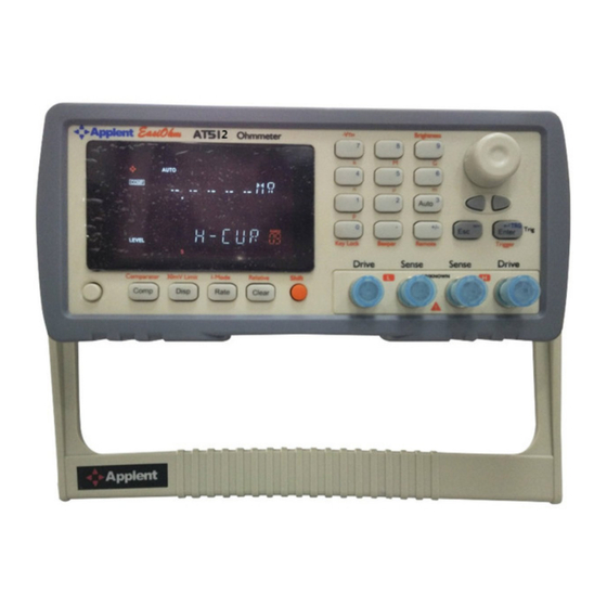
AT512 Precision Resistance Meter 3. Start up This chapter provides the following information: ⚫ A tour of front panel ⚫ A tour of rear panel ⚫ How to Remove the Handle ⚫ Power Up ⚫ Display information ⚫ Measurement configuration A tour of front panel 3.1.1... - Page 11 Start up Orange Words on Panel represents 2 Function; Blue Words on Button represents Numeric Key. Figure 3-2 Keypad I I-Mode Relative Comparator 30mV Limit -% Rate Comp Clear Figure 3-3 Keypad II Primary Function Black Words on Button represents 1 Function;...
-
Page 12: Vfd
AT512 Precision Resistance Meter 30mV-limited *The function is invalid in the version. Select test current modes: Test Current Modes High current(H-Cur)、Low current(L-Cur)and Plus current(P-Cur) Relative Value Relative value display. The REL indicator is ON, the value is the Correction value. -
Page 13: Rear Panel
Start up Fail. Good. Above the upper limit value. Pass. Blow the lower limit value. COMP Comparator function is ON. Setup comparator status. HIGH Upper limit value. Lower limit value. Keypad Locked. Data Hold. LEVEL Test Current Mode External Trigger Mode. -
Page 14: Power Up
The power-on default will be the last configuration you saved. 3.3.4 Warm-up Time AT512 is ready to be used as soon as the power-up sequence has completed. However, to achieve the accuracy rating, warm up the instrument for 15 minutes. Measurement configuration 3.4.1... -
Page 15: Range
No putting current source, voltage source directly access test side. Energy storage device access to testing after discharging. 3.4.2 Range In the automatic range status, AT512 will choose the fit range by the following table: Table 3-1 Range Reference Down Resistance 10m... -
Page 16: Calibration (Short Zeroing)
AT512 Precision Resistance Meter 3.4.4 Calibration (Short Zeroing) 1.Press Clear key to the Clearing status and make the test clips short-circuit like the following way before zeroing. Figure 3-5 ight Way Figure 3-6 rong Way 2.Press Enter key to Calibration.The meter zeroing all ranges in the automatic range or the present range in the hold range. -
Page 17: Keypad Locked
Start up α- Temperature coefficient of reference temperature F1 - Without compensation value F2 - Temperature compensated value 3.4.7 Keypad Locked Press Shift Key Lock key to lock/unlocked the keypad. The Key Lock key is only available and the other keys are in vain when the keypad is locked ... -
Page 18: Comparator
Setup Beep Turn ON/OFF Comparator AT512’s boot comparator is ON in default, you can press Comp key to close. When the comparator function is OFF, apparatus, sorting system will no longer work at the same time with the Handler interface signals on the comparator output will be shut down. -
Page 19: Setup Beep
Comparator measurement status. Using skill:The present value is flashed ,you can press digits to input the value TIP: directly and it’s not necessary to press the Enter key first to enter the input status. NOTE:In the number input status, press Enter key, the unit is 1. For example:... -
Page 20: Handler Interface
The AT512’s built-in handler interface outputs signals that indicate the end of a measurement cycle, the result of bin sorting by the comparator. In addition, the instrument accepts input of external trigger. You can use these signals to easily integrate the AT512 with system controller. Pin Assignment Figure 5-1 Pin Assignment ◼... -
Page 21: Connection
Handler Interface 11101 10101 01101 00101 11100 10100 01100 00100 11011 10011 01011 00011 11010 10010 01010 00010 11001 10001 01001 00001 11000 10000 01000 00000 Unchanged ◼ External signal output Unused Unused Unused Unused Unused Unused “Parameter below lower limit” signal. This signal is output when the parameter is below the lower limit. - Page 22 AT512 Precision Resistance Meter Optical isolation. Low level is enabled. Maximum voltage: Power supply voltage. Maximum current:5~8mA。 Input signal: Optical isolation. Low level is enabled. Maximum current:50mA NOTE: Power supply voltage should not exceed the power requirements to avoid damage to the interfaces.
-
Page 23: Specification
Specification 6. Specification Appendix provides the following information: ⚫ Feature Index ⚫ General Specification ⚫ Dimensions Feature Index The following data are measured under the following conditions: Temperature:23℃± 5℃ Humidity: <=80% R.H Correction:Short Zeroing Warm up:60 minutes and more Calibration Time:6 months Sample Speed:... - Page 24 AT512 Precision Resistance Meter Parameters: Direct reading ,(ABS),(%)and Sorting Results.. Resistance Range:0.1u ~ 1G, Minimum Resolution:0.1。 Maxim Display Value: 10500 Test Signal: 10m~10k ( Constant Current Test ),100k~100M ( Constant Voltage Test ). Trigger Mode:Internal、External and Remote. Range: Automatic and Manual Correction:...
-
Page 25: Dimensions
Specification Dimensions @ Instruments -AT512 User’s Guide-English ©2005-2013 Applent Instruments Inc.
Need help?
Do you have a question about the AT512 and is the answer not in the manual?
Questions and answers