Table of Contents
Advertisement
Quick Links
User's Guide
AT515
Rev.A5
Precision Resistance Meter
®
~
Applent Instruments Ltd.
@
Address: Dangnan Industrial Zone,
Changzhou, Jiangsu, China (PRC)
Post Code: 213014
Tel: 0086-0519-88805550 / 89966117 / 89966227 / 89966337
Fax: 0086-0519-89966550
sales@applent.com
Sales Email:
tech@applent.com
Tech Email:
http://www.applent.com
Advertisement
Table of Contents

Related Manuals for Applent Instruments AT515


Summary of Contents for Applent Instruments AT515
- Page 1 User’s Guide AT515 Rev.A5 Precision Resistance Meter ® Applent Instruments Ltd. Address: Dangnan Industrial Zone, Changzhou, Jiangsu, China (PRC) Post Code: 213014 Tel: 0086-0519-88805550 / 89966117 / 89966227 / 89966337 Fax: 0086-0519-89966550 sales@applent.com Sales Email: tech@applent.com Tech Email: http://www.applent.com...
-
Page 2: Certification, Limited Warranty, & Limitation Of Liability
CERTIFICATION, LIMITED WARRANTY, & LIMITATION OF LIABILITY Applent Instruments, Inc. (shortened form Applent)certifies that this product met its published specifications at the time of shipment from the factory. Applent further certifies that its calibration measurements are traceable to the People’s Republic of China National Institute of Standards and Technology, to the extent allowed by the Institution’s calibration facility or by the calibration facilities of other International Standards Organization... -
Page 3: Table Of Contents
Unpacking and Preparation Contents CERTIFICATION, LIMITED WARRANTY, & LIMITATION OF LIABILITY ............. 2 Contents ..................................3 Figure Contents................................5 Table Contents ................................6 1. Unpacking and Preparation ..........................7 1.1 Incoming Inspection .......................... 7 1.2 Setting up Fuse ..........................7 1.3 ... - Page 4 AT515 User's Guide 7.2 Power Rating ........................... 30 7.3 Electrical Characteristics ......................... 30 7.3.1 Input Signal: ..........................30 7.3.2 Output Signal: .......................... 30 7.3.3 Power supply ........................... 30 7.3.4 Schematic ..........................30 8. Remote Control ..............................32 8.1 About RS-232C ..........................32 ...
- Page 5 Unpacking and Preparation Figure Contents Figure 1-1 How to remove the handle ......................9 Figure 3-1 Front panel ..........................12 Figure 3-2 Real Panel ..........................12 Figure 3-3 Connect to DUT ........................13 Figure 4-1 <MEAS DISPLAY> Page ......................15 Figure 4-2 ...
-
Page 6: Table Contents
Table 3-2 Real panel description ......................13 Table 4-1 Range Mode ........................... 16 Table 4-2 Effective measurement range of AT515 ................... 16 Table 7-1 Description of Handler Interface Signals ................. 29 Table 8-1 RS-232 connector pinout ......................32 Table 9-1 ... -
Page 7: Unpacking And Preparation
Unpacking and Preparation Unpacking and Preparation This chapter describes how to set up and start the AT515 DC Resistance Meter. Incoming Inspection Power Requirements Setting up the Fuse How to Remove the Handle Environmental Requirements Cleaning... -
Page 8: Cleaning
Altitude: 0 to 2,000m Vibration: Max. 0.5 G, 5 Hz to 500 Hz Cleaning To prevent electrical shock, disconnect the AT515 power cable from the receptacle before cleaning. Use a dry cloth or a cloth slightly dipped in water to clean the casing. -
Page 9: How To Remove The Handle
Unpacking and Preparation A handle kit is attached to the AT515: Figure 1-1 How to remove the handle 1 Retracted 3 Carrying Position 2 Extended Remove Handle(Lift the handle perpendicular to the unit while pulling it in the direction of 1.)... -
Page 10: Overview
With its built-in comparator, the AT515 can output comparison/decision results for sorting components into a maximum of ten bins. Furthermore, by using the handler interface, the AT515 can be easily combined with a component handler, and a system controller to fully automate component testing, sorting, and quality-control data processing. -
Page 11: Basic Accuracy
Overview 2.2.4 Basic Accuracy Slow Speed: 0.01% Medium Speed: 0.05% Fast and Ultra Speed: 0.1% Main Functions 2.3.1 Correction Function SHORT correction: Eliminates measurement errors due to stray parasitic impedance in the test fixtures. 2.3.2 Comparator Function (Sorting) Bin sort The primary parameter can be sorted into BIN1-BIN9, and HI/IN/LO. The sequential mode or tolerance mode can be selected as the sorting mode. -
Page 12: Startup
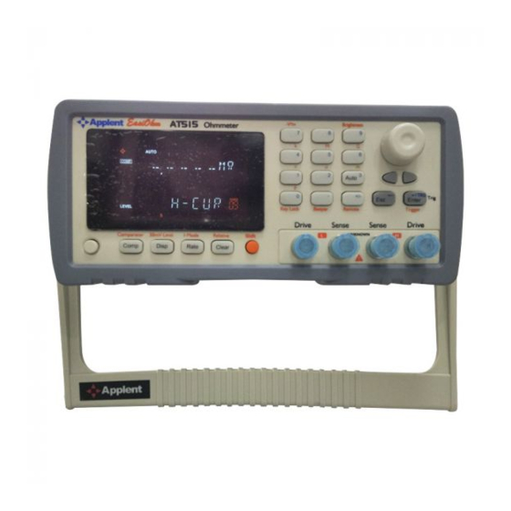
AT515 User's Guide Startup This chapter describes names and functions of the front panel, rear panel, and screen display and provides the basic procedures for operating AT515. Front panel summary Rear panel summary Power On/Off Connect to Device under Test Front panel Figure 3‐1... -
Page 13: Power On/Off
Power ON. Power OFF. Warm‐up Time AT515 is ready to be used as soon as the power-up sequence has completed. However, to achieve the accuracy rating, warm up the instrument for 30 minutes. Connect to Device under Test (DUT) Red logo testing BNC cables into the H in the first rotation;... - Page 14 AT515 User's Guide Warning: No putting current source, voltage source directly access test side. Energy storage device access to testing after discharging.
-
Page 15: Meas Display> Page
Figure 4‐1 <MEAS DISPLAY> Page 4.1.1 Trigger Mode [TRIG] SCPI Command: TRIGger:SOURce {INT,MAN,EXT,BUS} AT515 supports four trigger modes: INT (internal), EXT (external), MAN (manual) and BUS (RS-232). Trigger Mode Description AT515 continuously repeats the measurement cycle. AT515 performs one cycle of measurement each time you press the [Trig] key. -
Page 16: Range [Range]
SCPI Command: FUNCtion:RANGe {<range number>,min,max} SCPI Command: FUNCtion:RANGe:MODE {AUTO,HOLD,NOMinal} Table 4‐1 Range Mode Mode Function overview Advantage Disadvantage Auto AT515 sets the optimum range You don’t need to The measurement range automatic. select range. time is longer due to the ranging time Hold... -
Page 17: Comparator Bins [Comp]
Handler interface signals on the comparator output will be shut down. Please refer to the comparator section for detail. AT515’s built-in comparator can sort devices into a maximum of 10 bins (BIN1 to BIN9 and NG) using a maximum of 10 pairs limits Figure 4‐2... -
Page 18: Measurement Speed [Rate]
AT515 User's Guide 02-BINS 03-BINS 04-BINS 05-BINS 06-BINS 07-BINS 08-BINS 09-BINS 10-BINS 4.1.4 Measurement Speed [RATE] SCPI Command: FUNCtion:RATE {SLOW,MED,FAST,ULTRA,ULTRA2} SLOW, MED, FAST, ULTRA and ULTRA2 (DISPLAY OFF) can be selected for AT515. SLOW mode will result in more stable and accurate measurement result. -
Page 19: Setup> Page
<SETUP> Page <SETUP> Page This section includes the following information: SETUP page Temperature Compensation Setup SHORT Correction Comparator Setup Every time or everywhere you can press the [Setup] key to open the <SETUP> page. In <SETUP> page, the Instrument does not display test result and sorting result, and NOTE testing is stopped. -
Page 20: Trigger Edge [Trig-Edge]
Soft key Function RISING EDGE FALLING EDGE 5.1.3 Turn Temperature Compensation ON/OFF SCPI Command: FUNCtion:TC {ON,OFF,1,0} The AT515 built in Temperature Compensation Interface. The Temperature Compensation Formula is: Where, T0: Reference Temperature T: Current Room Temperature α : Temperature coefficient of reference temperature (%) -
Page 21: Short-Circuit Clear Zero
Please make the test clips short-circuit like the following way: Step 5. Press [OK] soft key. The AT515 measures short resistance at the all ranges. During the measurement, an “SHORT measurement in progress” dialog message is shown on the display. -
Page 22: Comparator Limit Mode [Mode]
AT515’s built-in comparator can sort DUTs into a maximum 11 levels (BIN1 through BIN10 and BIN0 (OUT) using up to 10 sets limit. To take full advantage of the comparator, AT515 was equipped a handler interface for use in conjunction with the comparator. All BIN1~BIN10 and HI/IN/LO bins signal can output to yours PLC via the handler interface. -
Page 23: Example Of Sorting In Tolerance Mode
<SETUP> Page ● Includes the point ○ Excludes the point Absolute value () = UNKNOWN value – nominal value Deviation percentages (%) = Absolute value () / nominal value × 100% Figure 5‐5 Example of sorting in tolerance mode ● Includes the point ○... -
Page 24: Nominal Value For Tolerance Mode
5.3.3 Lower and Upper Limits SCPI Command: COMParator:BIN < 1~10>,<LOWER>,<UPPER> AT515’s built-in comparator can sort DUTs into a maximum 10 levels (Bin1 thru Bin10 and OUT) using up to 10 sets limits. To enter the limit values Step 1. Press the [Meas] or [Setup] key Step 2. -
Page 25: System Configurations
Figure 6‐1 <SYSTEM CONFIG> Page 6.1.1 Setting the system date and time AT515 features a built-in 24-hour clock. To change the date Step 1. Press the [Meas] or [Setup] key Step 2. Press the [SYSTEM] bottom soft key. Step 3. Use the cursor key to select date field Step 4. -
Page 26: Account Setting
Decreases the second in steps of 1. 6.1.2 Account Setting The AT515 has two accounts, administrator and user. Administrator: All functions can be configured by administrator except <SYSTEM SERVICE> page. User: All functions can be configured by user except < SYSTEM SERVICE> page and <FILE>... -
Page 27: Rs-232 Baud Rate [Baud]
Beep while the comparator sorting result is NG 6.1.4 RS‐232 Baud Rate [BAUD] Before you can control the AT515 by issuing RS-232 commands from built-in RS-232 controller connected via its DB-9 connector, you have to configure the RS-232 baud rate. The AT515’s built-in RS-232 interface uses the SCPI language. -
Page 28: Rs-232 Result Send Mode [Result Send]
FETCH Acquire the test result by sending “FETCH?” command only. AUTO AT515 return the result every EOM <SYSTEM INFO> Page When press the [Meas] or [Setup] key followed by [SYSTEM] bottom soft key, and press [SYSTEM INFO] soft key, the <SYSTEM INFO> page appears. -
Page 29: Handler Interface
In addition, the instrument accepts input of external trigger. You can use these signals to easily integrate the AT515 with a component handler or system controller. This means that you can fully automate such tasks as component inspection, component sorting, and processing of quality management data for higher manufacturing efficiency. -
Page 30: Power Rating
AT515 User's Guide /BIN1 Output 0:GD Internal GND 27-28 Internal GND Power Common signal of internal VCC. External GND 29-30 External GND Power Common signal for external DC current External VCC 33-34 Internal VCC Power Internal VCC (5VDC) External VCC (3.3V~35V) -
Page 31: Typical Circuit Diagram Of Handler Interface Output Signals
Handler Interface JP204 R24 3 EXVCC TRIG U221 P521 JP205 Figure 7‐3 Typical Circuit Diagram of Handler Interface Output signals. EXT.DCV 4.99k OUTPUT GN D... -
Page 32: Remote Control
Select Baud Rate. About SCPI AT515 can use the RS-232 interface or USB interface to communicate with the computer to complete all the instrument functions. About RS‐232C You can connect a controller (i.e. PC and PLC) to the RS-232 interface using Applent RS-232 DB-9 cable. -
Page 33: About Usb-Serial Interface (Option)
Remote Control About USB‐Serial Interface (Option) The USB-Serial Interface allows you to connect AT515 to a USB port on your PC. NOTE: Please install the USB-Serial driver before using USB-Serial Interface. The Applent USB-Serial interface model is ATN2. Figure 8‐2 USB‐Serial Interface ATN2 To Select Baud Rate Before you can control the AT515 by issuing RS-232 commands from built-in RS-232 controller connected via its DB-9 connector, you have to configure the RS-232 baud rate. - Page 34 AT515 User's Guide RS-232 interfaces. NOTE: AT515 ONLY supports the SCPI Language.
-
Page 35: Command Reference
The common commands are defined in IEEE std. 488.2-1987, and these commands are common for all devices. The SCPI commands are used to control all of the AT515's functions. The SCPI commands are tree structured three levels deep. The highest level commands are called the subsystem commands in this manual. - Page 36 For example, root:com3:com5 ppp; : root:com1 ppp The AT515 accepts the three forms of the same SCPI commands: all upper case, all lower case, and mixed upper and lower case.
-
Page 37: Header And Parameters
Command Reference Header and Parameters The commands consist of a command header and parameters. (See the following.) For example comp:nom 100.0e3 Header Parameter Headers can be of the long form or the short form. The long form allows easier understanding of the program code and the short form allows more efficient use of the computer. -
Page 38: Display Subsystem
AT515 User's Guide ERRor Subsystem Common Command: IDN? DISPlay Subsystem The DISP Subsystem command group sets the display page. Figure 9‐2 DISP Command Tree DISPlay :PAGE {MEASurement, SETUp, COMParator,SYSTem, SYSTEMINFO(SINF)} :LINE <string> 9.6.1 DISP:PAGE The :PAGE command sets the display page. -
Page 39: Function:range
Command Reference FUNCtion :RANGe {Range Number,max,min} :MODE {AUTO,HOLD,NOMinal} :RATE {SLOW,MED,FAST,ULTRA,ULTRA2} : COEFficient <float> :REFEr <float> 9.7.1 FUNCtion:RANGe The FUNCtion:RANGe command sets the range. Command Syntax FUNC:RANGe <0-11,MIN,MAX> Parameter Where, <0-11,MIN, MAX> is: 0-9, The range number MIN, =Range 0 MAX, =Range 11 Example SEND>... -
Page 40: Function:tc: Coefficient
AT515 User's Guide Query Syntax FUNC:TC? Query Response {ON,OFF} 9.7.5 FUNCtion:TC: COEFficient The FUNC:TC:COEF command sets the material coefficient. Command Syntax FUNCtion:TC:COEFficient {float} Example SEND> FUNC:TC:COEF 0.393 //the unit is % <NL> Query Syntax FUNC:TC:COEF? Query Response {fixfloat} Example SEND> FUNC:TC:COEF? <NL>... -
Page 41: Comparator:mode
Command Reference 9.8.2 COMParator:MODE The :COMParator:MODE command sets the limit mode of the comparator function. Command Syntax COMParator:MODE {ABS,PER,SEQ} Parameter Where,{ABS,PER,SEQ} is: Absolute tolerance mode Percent tolerance mode Sequential mode Example SEND> COMP:MODE PER <NL> Query Syntax COMParator:MODE? Query Response {abs,per,seq} Example SEND>... -
Page 42: Trigger Subsystem
AT515 User's Guide Query Response <float:lower limit>,<float:upper limit> Example SEND> COMP:BIN? 2 <NL> RET> 1.000000e-00,2.000000E-00 <NL> TRIGger Subsystem The TRIGger subsystem command group is used to enable a measurement and to set the trigger mode. Figure 9‐5 TRIGger Subsystem Command Tree TRIGger [:IMMediate] :SOURce {INT,MAN,EXT,BUS} 9.9.1... -
Page 43: Fetch Subsystem
Command Reference 9.10 FETCh Subsystem The FETCh subsystem command group is a sensor-only command which retrieves the measurement data taken by measurement(s) initiated by a trigger, and places the data into the output buffer. Figure 9‐6 FETCh Subsystem Command Tree FETCh? 9.10.1 FETCh? The FETCh? retrieves the latest measurement data and comparator result. Query Syntax FETCh? Query Response <float>,<comparator result>... -
Page 44: Error Subsystem
AT515 User's Guide 9.13 ERRor Subsystem The ERRor subsystem retrieves last error information. Query Syntax ERRor? Query Response Error string Example SEND> ERR? <NL> RET> no error. <NL> 9.14 IDN? The *IDN? query returns the instrument ID. Query Syntax IDN? Or *IDN? -
Page 45: Specification
Specification Specification This chapter describes the specifications and supplemental performance characteristics of the AT515: Specifications Dimension Accuracy is defined as meeting all of the following conditions. Temperature: 23℃±5℃ Humidity: 65% R.H. Zeroing: Open and Short Correction Warm up time is 30 min or more. -
Page 46: General Specification
1,200,000 Ranging: Auto, Hold and Nominal range. Correction Function: SHORT-CIRCUIT Clear Zero Comparator: Total 13 Bins, 10 bins GD, 3 bins HI/IN/LO <AT515> Beep Feature: OFF/GD/NG Trigger Mode: Internal, Manual, External and Bus Trigger. Built-in Interface: Handler interface, RS232 interface, Temperature Compensation interface. -
Page 47: Dimensions
Specification 10.3 Dimensions Figure 10‐1 Dimensions @ Instruments -AT515 User’s Guide- English ©2005-2015 Applent Instruments Inc.
Need help?
Do you have a question about the AT515 and is the answer not in the manual?
Questions and answers