Table of Contents
Advertisement
Quick Links
1
AT510x DC Resistance Meter
! $Instruments
Applent Instrument, Inc.
Dangnan Industrial Park,Tianning District,
Changzhou, Jiangsu, China [213014]
Tel:0519-88805550 / 89966117/89966227
Fax:0519-89966550
http://www.applent.com
Sales Email:
sales@applent.com
Tech Email:
tech@applent.com
©2005-2012 Applent Instruments, Inc.
Rev.D
[AT510PRO/510/510SE/510L/510M
User's Manual
DC RESISTANCE METER]
Advertisement
Table of Contents

Related Manuals for Applent Instruments AT510PRO


Summary of Contents for Applent Instruments AT510PRO
- Page 1 AT510x DC Resistance Meter ! $Instruments Applent Instrument, Inc. Dangnan Industrial Park,Tianning District, Changzhou, Jiangsu, China [213014] Tel:0519-88805550 / 89966117/89966227 Fax:0519-89966550 http://www.applent.com Sales Email: sales@applent.com Tech Email: tech@applent.com ©2005-2012 Applent Instruments, Inc. Rev.D [AT510PRO/510/510SE/510L/510M User’s Manual DC RESISTANCE METER]...
-
Page 2: Safety Summary
When you notice any of the unusual conditions listed below, immediately terminate operation and disconnect the power cable. Please Contact Applent Instruments Incorporation sales representative for repair of the instrument. If you continue to operate without repairing the instrument, there is a potential fire or shock hazard for the operator. -
Page 3: Certifiaction, Limited & Limitation Of Uability
AT510x DC Resistance Meter CERTIFIACTION, LIMITED & LIMITATION OF UABILITY Applent Instruments, Inc. (shortened form Applent)certifies that this product met its published specifications at the time of shipment from the factory. Applent further certifies that its calibration measurements are traceable to the People’s Republic of China National Institute of Standards and Technology, to the extent allowed by the... -
Page 4: Table Of Contents
Unpacking and Inspection Contents Safety Summary ..............................2 CERTIFIACTION, LIMITED & LIMITATION OF UABILITY ..............3 Contents ................................4 Unpacking and Inspection ..........................6 Packing List ............................6 Power Supply ............................. 6 Setting up Fuse ..........................7 Environmental Requirements ......................7 Cleaning ............................. - Page 5 AT510x DC Resistance Meter High Current Test Mode ........................24 Low Current Test Mode(AT510PRO/AT510) .................. 25 Plus Current Test Mode (AT510PRO/AT510) ................. 25 General Specification ........................26 Dimensions ............................27 Models ................................28...
-
Page 6: Unpacking And Inspection
Unpacking and Inspection Unpacking and Inspection This chapter provides the following information: Packing List Power Supply Setup Fuse Operating Environment Cleaning How to Remove the Handle Packing List After you receive the instrument, carry out checks during unpacking according to the following procedure. -
Page 7: Setting Up Fuse
AT510x DC Resistance Meter Setting up Fuse ~Line: 47.5Hz - 52.5Hz 198VAC - 242VAC 10VA MAX Fuse: 250V, 0.5AH Slow Blow Figure1-1 Fuse Holder Please use the following fuse type : UL/CSA type, Slow-Blow, 5×20-mm miniature fuse, 0.5A, 250 V . Environmental Requirements Ensure that the operating environment meets the following requirements. -
Page 8: How To Remove The Handle
Unpacking and Inspection How to Remove the Handle A handle kit is attached to the AT512: Figure 1-1 Hand Handle 1 Retracted Carrying Position 2 Extended Remove Handle ( L ift the handle perpendicular to the unit while pulling it in the direction of ①.)... -
Page 9: General
Models Introduction Model Resistance Range Accuracy AT510PRO 0.05% 1mΩ-20MΩ 0.05% AT510 1mΩ-3MΩ 0.05% AT510SE 10mΩ-300kΩ... -
Page 10: Feature Overview
Short Zeroing Comparator (sorting) function: Built-in 30 sorting files (AT510Pro/AT510/AT510SE) and Output 3 levels (HI, IN and Low) or (GD, NG), display, beep sound. ·Display: Direct display on the VFD displayer. ·Output: Output the sorting results by the Handler interface or RS232C interface. -
Page 11: Start Up
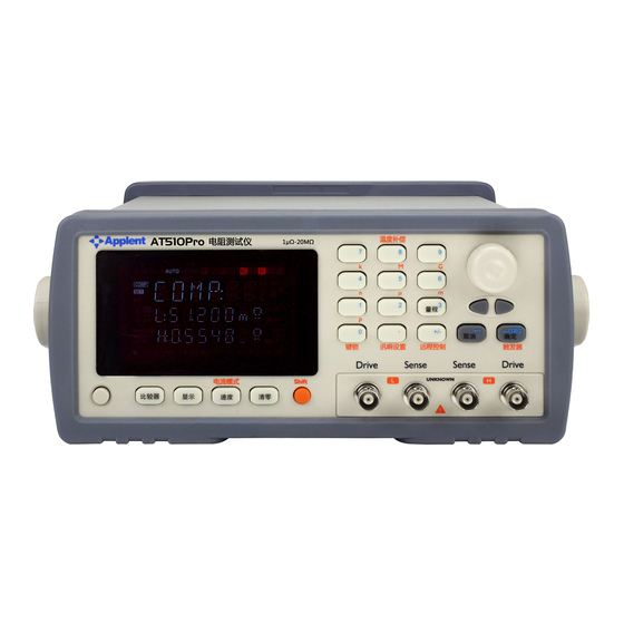
AT510x DC Resistance Meter 3. Start up This chapter provides the following information: A tour of front panel A tour of rear panel Power Up Display information Measurement configuration Front panel Figure 3-1 3.1.1 Front Panel Overview Front Panel Overview Brightness Range... - Page 12 Start up Comparator 30mV Limit I-Mode Relative ∆ -% Comp Rate Clear Figure 3-3 Keypad II Brightness Range Data ← Trig Beep Enter Hold Table 3-2 Primary Functions description Key Lock Beeper Remote Trigger Function Comparator Setup comparator ∆-∆% *The function is invalid. Speed Measurement speed:(Slow),(Medium),(Fast).
-
Page 13: Vfd
AT510x DC Resistance Meter k, M, G). Figure 3-4 3.1.3 Applent’s Trade Mark. Remote Control Indication. Beep is ON. AUTO Range automatic indication. Relative function is ON. Fail. Good. Above the upper limit value. Pass. Blow the lower limit value. COMP Comparator function is ON. -
Page 14: Power Up
Start up RS232C interface. Handler interface. AC power cord receptacle and fuse holder Power Up 3.3.1 Line Power Connection Power ON. Power OFF. 3.3.2 Power-up Sequence : AT510x is power up, it performs self-tests on its Flash-Rom, RAM and momentarily lights all segments and indicators. -
Page 15: Test Current Modes
Detailed test current modes see Appendix A. 3.4.3 Range Table 3-4 Range no., reference Resistance and Range change process(AT510Pro) In the automatic range status, AT510x will choose the fit range by the following table: Reference Resistance Down ... -
Page 16: Speed
3 . P ress Esc or when zeroing is over, return to the measurement status. 3.4.6 Relative Value for Temperature Compensation AT510pro, AT510 (Standard), AT510se (Optional), AT510L, AT510M (invalid) Press Shift Relative key to Turn ON/OFF the relative function. The REL indicator is OFF;... -
Page 17: 20Mv Limit(The Function Is Invalid In The At510X's Version
20mV limit( The function is invalid in the AT510x’s version.) The function is invalid in the AT510x’s version. 3.4.10 Temperature Correction Function AT510PRO, AT510: Standard function.AT510SE: Optional function.AT510L/510M: Invalid function. The temperature probe is plugged into the jack, the function is enabled. -
Page 18: Comparator
Comparator 4. Comparator This chapter provides the following information: Turn ON/OFF Setup comparator record number file Setup nominal value and limit value Setup Beep Turn ON/OFF Comparator AT510X’s comparatorcan be turned OFF by pressing Comp key. When the comparator function is OFF, sorting system will no longer work and the Handler interface signals on the comparator output will be shut down. -
Page 19: Turn On/Off Beep
Comparator In the range hold status (“AUTO” indication is OFF), Meter will select the range by the upper limit value when it is exit setup status. 4.1.3 Turn ON/OFF Beep Press Beep key to turn ON/OFF beep function. Indication is ON, the beep function is ON. 4.1.4 Setup Beep 1. -
Page 20: Handler Interface
Handler Interface Handler Interface Note: AT510PRO/AT510 (Standard interface), AT510SE/510L/510M(Optional interface). This chapter provides information of AT510x’s built-in handler interface. Include: • Pin Assignment • Circuit Diagram • Timing Chart The AT510x’s built-in handler interface outputs signals that indicate the end of a measurement cycle, the result of bin sorting by the comparator. -
Page 21: Connection Method
AT510x DC Resistance Meter 11000 10000 01000 00000 Unchanged External signal output Unused Unused Unused Unused Unused Unused “Parameter below lower limit” signal. This signal is output when the parameter is below the lower limit. Output the Pass signal. “Parameter beyond upper limit”... -
Page 22: Electrical Characteristics
Handler Interface pull-up resistance 50mADC max INPUT Negative logic 50mADC max EXT.DCV DC voltage input 35VDC max Electrical Characteristics 5.4.1 Input Signal: Each input signal is connected to the LED (cathode side) of the photo-coupler. The LED (anode side) is connected to the pull-up power supply voltage. 5.4.2 Output Signal: Each output signal is outputted via a open collector by using a photo-coupler. -
Page 23: Timing Chart
AT510x DC Resistance Meter Timing Chart T R I G E O C O U T P U T 有 效 t1 : M easurement time: Fast:66.7ms ,M edium :200ms ,Slow :330ms :1 ms :200 :0 ms... -
Page 24: Specification
Temperature:23℃±5℃ Humidity: <=80% R.H Correction:Short Zeroing Warm up:60 minutes and more Calibration Time:6 months High Current Test Mode Sample Speed: Fast: 60 meas/sec Medium: 15 meas/sec Slow: 2meas/sec AT510PRO: Maxim Medium & Test Open-circuit Range Display Resolution Fast Slow Current... -
Page 25: Low Current Test Mode(At510Pro/At510)
<1V 100mΩ 30Ω 30.000Ω 1mΩ 0.1%±5 670uA <1V 300Ω 300.00Ω 10mΩ 0.1%±5 67uA <1V 3kΩ 3.000kΩ 100mΩ 0.1%±5 67uA <1V Plus Current Test Mode (AT510PRO/AT510) Only for range below 300Ω, other ranges are the same with High Current. Sample Speed:... -
Page 26: General Specification
Comparator: Output NG-LO, GD-IN, NG-HI,built-in 30 sorting files. Beep: GD、NG、Open/Close Function and Adjust volume. Test Terminal: 4 terminals with ground shielding. Interface: Handler interface (AT510PRO/AT510/AT510SE) RS232 interface (AT510PRO/AT510/AT510SE) Programmed Language: SCPI Environment: Index: T & H: 15℃~35℃, <=80% RH Operating: T & H: 10℃~40℃, 10~90% RH Storage:... -
Page 27: Dimensions
AT510x DC Resistance Meter Dimensions... -
Page 28: Models
Function RS232C RS232C(Optional) Interface HANDLER HANDLER(Optional) Comparator Hi/IN/Lo/GD/NG Range Mode Automatic/Range Hold Display 30000 digitals (4-2/3) VFD Display Beeper GD/NG/OFF, adjust the volume Correction Short Zeroing Test Terminal 4-terminals Test @ Instruments AT510PRO/510/510L/510M/510SE User’s Manual English ©2005-2012 Applent Instruments Inc.
Need help?
Do you have a question about the AT510PRO and is the answer not in the manual?
Questions and answers