Table of Contents
Advertisement
Quick Links
v.LiNK Video-inserter
VL2-RTI11-5
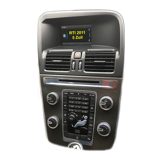
Compatible for
Volvo vehicles
with
RTI 2011
infotainment and 5 inch monitor
Video-inserter with rear-view camera input and 2 additional video inputs
Product features
Video-inserter for factory-infotainment systems
1 CVBS Rear-view camera video-input
2 CVBS video-inputs for after-market devices (e.g. USB-Player, DVB-T2 tuner, ...)
Built-in Audio-switch (no audio-insertion)
Automatic switching to rear-view camera input on engagement of the reverse gear
Video-in-motion (ONLY for connected video-sources)
Video-inputs PAL and NTSC compatible
Version 26.04.2021
HW: 16(V65)
VL2-RTI11-5
Advertisement
Table of Contents

Related Manuals for v.link VL2-RTI11-5


Summary of Contents for v.link VL2-RTI11-5
- Page 1 Video-inserter VL2-RTI11-5 Compatible for Volvo vehicles with RTI 2011 infotainment and 5 inch monitor Video-inserter with rear-view camera input and 2 additional video inputs Product features Video-inserter for factory-infotainment systems 1 CVBS Rear-view camera video-input 2 CVBS video-inputs for after-market devices (e.g. USB-Player, DVB-T2 tuner, ...) ...
-
Page 2: Table Of Contents
Connection – External keypad 2.10. Picture settings 3. Video interface operation 3.1. By infotainment button 3.2. By external keypad 3.3. By white wire of the 6pin cable 4. Specifications 5. FAQ – Trouble Shooting-Interface functions 6. Technical support Version 26.04.2021 HW: 16(V65) VL2-RTI11-5... -
Page 3: Prior To Installation
Read the manual prior to installation. Technical knowledge is necessary for installation. The place of installation must be free of moisture and away from heat sources. 1.1. Delivery contents Take down the serial number of the interface and store this manual for support purposes: ____________________ Version 26.04.2021 HW: 16(V65) VL2-RTI11-5... -
Page 4: Checking The Compatibility Of Vehicle And Accessories
Boxes and connectors 1.3.1. Video Interface The video-interface converts the video signals of connected after-market sources in a factory monitor compatible picture signal which is inserted in the factory monitor, by using separate trigger options. Version 26.04.2021 HW: 16(V65) VL2-RTI11-5... -
Page 5: Can-Bus Box
PDC No function set to OFF No function set to OFF No function set to OFF After each Dip-switch-change a power-reset of the Can-box has to be performed! See the following chapters for detailed information. Version 26.04.2021 HW: 16(V65) VL2-RTI11-5... -
Page 6: Enabling The Interface's Video Inputs (Dip 2-3)
Place of installation – video interface, CAN-bus box and daughter PCB The interface box and the CAN-bus box are prepared to be connected behind the vehicle`s monitor. The daughter PCB has to be installed inside the monitor. Version 26.04.2021 HW: 16(V65) VL2-RTI11-5... -
Page 7: Connection Schema
2.2. Connection schema Version 26.04.2021 HW: 16(V65) VL2-RTI11-5... -
Page 8: Connection - Video-Interface To Power/Can
Connect the 4 Power/CAN wires to the vehicle’s Power/CAN supply harness which is connected to the monitor’s 16pin connector. Note: No liability for vehicle wire colours and pin definition! Changes by the vehicle manufacturer are possible. The given information has to be verified by the installer. Version 26.04.2021 HW: 16(V65) VL2-RTI11-5... -
Page 9: Analogue Connection - Video-Interface
Note: The connection of the green wire (Reverse signal) will be described in chapter “After- market rear-view camera”. The white wire, can be used by +12V impulse to switch the enabled video sources, same as the keypad (see chapter “video interface-operation”). The grey wire remains unconnected. Version 26.04.2021 HW: 16(V65) VL2-RTI11-5... -
Page 10: Connection - Picture Signal Cable
180° position to the connector. Each deviation from a perfect contact position will curse faulty contact and even danger of short circuit 2) The ribbon cable’s contacting side always has to correspond to the contacting side of the connector, concerning the mounting position. Version 26.04.2021 HW: 16(V65) VL2-RTI11-5... -
Page 11: Connection - Video Sources
Connect the rear-view camera’s male RCA to the video interface’s female RCA „Camera IN”. Connect the male RCAs of possibly existing video sources 1 and 2 to the video interface’s female RCAs „Video IN1“ and „Video IN2“. Version 26.04.2021 HW: 16(V65) VL2-RTI11-5... -
Page 12: Audio-Switch And Audio-Insertion
RCA “Audio OUT”. Connect the audio-RCA connectors of possibly existing AV-sources 1 and 2 to the female RCAs of the audio cable’s „Audio 1 IN“ und „Audio 2 IN“. Version 26.04.2021 HW: 16(V65) VL2-RTI11-5... -
Page 13: After-Market Rear-View Camera
„CAMERA IN“ when the reverse gear is engaged. Additionally, the +12V (max. 500mA) power supply for the rear-view camera can be taken from the green wire of the 6pin to 8pin cable. Version 26.04.2021 HW: 16(V65) VL2-RTI11-5... -
Page 14: Case 2: Can-Box Does Not Receive The Reverse Gear Signal
Note: If, due to a missing CAN communication, the 6pin to 8pin cable has been connected the analogue way instead of the Can box, the green wire’s connection has also to be done as shown in the picture above. Version 26.04.2021 HW: 16(V65) VL2-RTI11-5... - Page 15 Connect the keypad’s female 4pin connector to the video-interface’s male 4pin connector. Note: Even if the switching through several video sources by the keypad mightn’t be required, the invisible connection and availability is strongly recommended. Version 26.04.2021 HW: 16(V65) VL2-RTI11-5...
-
Page 16: Picture Settings
The following settings are available: Contrast Brightness Saturation Sharpness AV1/2 no function RGB in no function Press the MENU button twice to set the picture position (another menu opens): V POS vertical position H POS horizontal position Version 26.04.2021 HW: 16(V65) VL2-RTI11-5... -
Page 17: Video Interface Operation
(press 2-3 seconds). 3.3. By white wire of the 6pin cable Alternatively, or additionally to the factory infotainment buttons, the 6pin cable’s white wire can be used to switch the enabled inputs (with +5V or+12V impulse. Version 26.04.2021 HW: 16(V65) VL2-RTI11-5... -
Page 18: Specifications
0.7V with 75 Ohm impedance Temperature range -40°C to +85°C Dimensions video-box 159 x 25 x 108 mm (B x H x T) Dimensions CAN-box 72 x 22 x 43 mm (B x H x T) Version 26.04.2021 HW: 16(V65) VL2-RTI11-5... -
Page 19: Faq - Trouble Shooting-Interface Functions
Camera input picture fluorescent light which shines Test camera under natural light outside the garage. flickers. directly into the camera. Camera input picture is Protection sticker not Remove protection sticker from lens. bluish. removed from camera lens. Version 26.04.2021 HW: 16(V65) VL2-RTI11-5... -
Page 20: Technical Support
Please note that direct technical support is only available for products purchased directly from NavLinkz GmbH. For products bought from other sources, contact your vendor for technical support. NavLinkz GmbH distribution/tech dealer-support Heidberghof 2 D-47495 Rheinberg +49 2843 17595 00 Email mail@navlinkz.de 10R-05 0068 Made in China Version 26.04.2021 HW: 16(V65) VL2-RTI11-5...
Need help?
Do you have a question about the VL2-RTI11-5 and is the answer not in the manual?
Questions and answers