
Related Manuals for v.link VL2-MMI2G


Summary of Contents for v.link VL2-MMI2G
- Page 1 Video-inserter VL2-MMI2G for Audi with MMI2G navigation system Video-inserter with 2 video + RGB + rear-view camera input Version 07.04.2011...
-
Page 2: Table Of Contents
To receive a free update, the interface must be sent in at own cost. Labor cost for and other expenses involved with the software-updates will not be refunded. Version 07.04.2011 VL2-MMI2G... -
Page 3: Prior To Installation
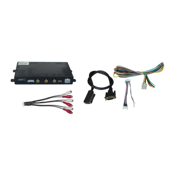
Technical knowledge is necessary for installation. The place of installation must be free of moisture and away from heat sources. 1.1. Delivery contents Take down the serial number of the interface and store this manual for support purposes: ____________________ Version 07.04.2011 VL2-MMI2G... -
Page 4: Checking The Compatibility Of Vehicle And Accessories
Only the enabled video inputs can be accessed when switching through the video sources. It is recommended to enable only the required inputs. Video-input ON (down) OFF (up) Dip 1 enabled disabled Dip 2 Video IN1 enabled disabled Dip 3 Video IN2 enabled disabled Version 07.04.2011 VL2-MMI2G... -
Page 5: Rear-View Camera Settings (Dip 5)
The Interface has to be installed into the LVDS leads between monitor control-box and monitor. The monitor control box is located at A6, A8 and Q7 behind the dash board, at A4 and A5 behind the air-conditioning control panel. Version 07.04.2011 VL2-MMI2G... -
Page 6: Connections
The vehicles MMI wire is on pin 16 of the 20pin connector of the monitor control-box. The connector can be red or black. No liability for vehicle wire colors and pin definition! Possible changes by the vehicle manufacturer. The given information must be verified by the installer. Version 07.04.2011 VL2-MMI2G... -
Page 7: Installation Procedure - Function Check
Then the AV-inputs will be controlled by the AUX-in interface (see manual of the AUX-1xx). Important! Do not connect the white wire additionally to pin 16 of the monitor control box when connected to the AUX-in interface. Version 07.04.2011 VL2-MMI2G... -
Page 8: Picture Settings
Audio pins Definition Audio input signal R/L of source IN2 Audio input signal R/L of source IN1 Audio output signal R/L of AUX-1xx, Gateway 500 or FM-modulator Ground No function Audio-switch-port Audio-cable Video-interface Version 07.04.2011 VL2-MMI2G... -
Page 9: Interface Operation
Dimensions (box only) B x H x T 182 x 24 x 100 mm 5. Technical Support NavLinkz GmbH Caraudio-Systems Vertriebs GmbH distribution/tech dealer-support distribution Eurotec-Ring 45 Rheinhorststr. 22 D-47445 Moers D-67071 Ludwigshafen am Rhein phone +49 2841 949970 email mail@navlinkz.de Version 07.04.2011 VL2-MMI2G...
Need help?
Do you have a question about the VL2-MMI2G and is the answer not in the manual?
Questions and answers