
Subscribe to Our Youtube Channel
Related Manuals for EcoWater Calex 11


Summary of Contents for EcoWater Calex 11
- Page 1 Installation and operating manual Water softener Calex 11, Calex 15, Calex 17 and Calex 22 Instructions for installation, operation and maintenance of your water softener Part No. 7340095 (Rev. F 5/1/15)
-
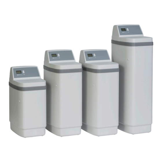
Page 2: Water Softener Dimensions
Water Softener Specifications Model 11L Model 15L Model 17L Model 22L Model Code 28,4 0,42 42,9 0,64 48,7 0,73 89,0 Rated Softening Capacity (mol @ kg. Salt Dose) 45,1 0,84 73,4 79,2 1,54 154,6 61,7 1,63 102,0 113,0 4,13 183,1 Rated Efficiency (mol/kg. -
Page 3: Programming The Water Softener
Programming the Water Softener Display UP button FIG. 2 RECHARGE button SELECT/MENU button DOWN button When the power supply is plugged into the electrical 1. Press the UP or DOWN buttons to set the outlet, a model code and a test number (example: present time. -
Page 4: Normal Operation
Programming the Water Softener During normal operation, the present time of day Hardness Unit Conversions shows in the display. gpg = °f x 0,584 French degrees (°f) °f = gpg x 1,712 OPTIONAL RECHARGE CONTROLS gpg = °dH x 1,043 Sometimes a manually initiated regeneration may be German degrees (°dH) °dH = gpg x 0,959... -
Page 5: Or 24 Hour Clock
Electronic Demand Timer Features / Options SET MAXIMUM DAYS BETWEEN 2. Press the SELECT/MENU button twice and “97” will flash in the display, alternating with the current REGENERATIONS setting (either “ON” or “OFF”). The default setting allows the timer to control regen- eration frequency based on water usage readings from the water meter. -
Page 6: Power Outage Memory
Electronic Demand Timer Features / Options ADJUST BACKWASH TIME AND RINSE POWER OUTAGE MEMORY TIME If electrical power to the softener’s control is lost, The timer can be changed to allow different backwash internal memory will maintain most settings such as and fast rinse times, if so desired. -
Page 7: Bypass Blending Valve
Bypass Blending Valve SERVICE POSITION The bypass blending valve works as a typical push- pull bypass valve, but has the added ability to finely (Normal Softener Operation) adjust hardness of the treated water leaving the water softener. If slightly harder water is desired than is Soft Water normally output by the water softener, this bypass Hard... -
Page 8: Refilling With Salt
Water Softener Maintenance REFILLING WITH SALT BREAKING A SALT BRIDGE Brine (salt dissolved in water) is needed for every Sometimes a hard crust or salt “bridge” forms in the regeneration. The water for making brine is metered brine tank. This is usually caused by high humidity into the salt storage area by the softener valve and or the wrong kind of salt. - Page 9 Water Softener Maintenance CLEANING THE NOZZLE & VENTURI A clean nozzle & venturi (See Figure 17) is necessary for the water softener to work properly. This small unit creates the suction to move brine from the brine O-Ring Seal tank into the resin tank. If it should become plugged Screen with dirt, silt, sand, etc., the water softener will not Support...
-
Page 10: Troubleshooting Guide
Troubleshooting TROUBLESHOOTING GUIDE PROBLEM CAUSE CORRECTION No soft water No salt in the storage tank. Add salt (See Page 7) and then initiate a “Recharge now,” as shown on Page 3. Salt is “bridged.” Break salt bridge (See Page 7) and then initiate a “Recharge now,”... -
Page 11: Automatic Electronic Diagnostics
Troubleshooting AUTOMATIC ELECTRONIC DIAGNOSTICS MANUALLY INITIATED ELECTRONIC DIAGNOSTICS This water softener has a self-diagnostic function for Use the following procedures to advance the water the electrical system (except input power and water softener through the regeneration cycles to check meter). The computer monitors electronic compo- operation. -
Page 12: Resetting To Factory Defaults
Troubleshooting MANUAL ADVANCE REGENERATION CHECK continued from previous page 5. While in this diagnostic screen, the following This check verifies proper operation of the valve motor, information is available and may be beneficial for brine tank fill, brine draw, regeneration flow rates, and various reasons. - Page 13 Water Softener Exploded View Valve Assembly See Pages 14 & 15 for parts...
- Page 14 Water Softener Parts List Part No. Description Part No. Description Power Supply, 28V DC, Tank Neck Clamp Kit – 7331177 7337490 (includes 2 ea. of Key Nos. 1 & 2) with Snap-in Plugs for Europe & UK Retainer, Clamp (2 req.) 7250826 Power Cord á...
- Page 15 Valve Assembly Exploded View Wear Strip Seal Cross-section View...
-
Page 16: Valve Parts List
Valve Parts List Part No. Description Part No. Description Turbine & Support Assembly, 7338111 Screw, #6-19 x 3.5 cm (2 req.) – 7113040 including 2 O-Rings (See Key No. 7281291 Motor 71) & 1 ea. of Key Nos. 72 & 73 7337474 Motor Mount Turbine Support &...
Need help?
Do you have a question about the Calex 11 and is the answer not in the manual?
Questions and answers