
Related Manuals for Beko BEKOMAT 8


Summary of Contents for Beko BEKOMAT 8
- Page 1 EN - English Installation and operation manual Condensate drain BEKOMAT ® BEKOMAT ®...
- Page 2 Installation and operation manual BEKOMAT ®...
-
Page 3: Table Of Contents
Installation and operation manual Contents 1. Safety-related information ..........................4 1.1. Pictograms and safety symbols ........................ 4 1.1.1. In this documentation ................................4 1.1.2. On the device ..................................4 1.2. Signal words ............................4 1.3. General safety instructions ........................5 1.4. Transport and storage ..........................7 1.5. -
Page 4: Safety-Related Information
Installation and operation manual 1. Safety-related information 1.1. Pictograms and safety symbols 1.1.1. In this documentation General note Note the installation and operating manual General hazard symbol (danger, warning, caution) General hazard symbol (danger, warning, caution) for mains voltage and system compo- nents carrying mains voltage 1.1.2. -
Page 5: General Safety Instructions
Installation and operation manual 1.3. General safety instructions DANGER Insufficient qualification Inappropriate handling due to insufficient qualification can lead to serious property damage and personal injuries or death. • All the tasks described in this installation and operation manual may only be carried out by skilled technical personnel¹... - Page 6 Installation and operation manual Legal warranty and liability for property defects NOTE Claims based on legal or material defect liability as well as on the flawless functionality of the device can only be guaranteed by adhering to the following points: •...
-
Page 7: Transport And Storage
Despite our best efforts, transport damage cannot be excluded. Please therefore remove all packaging material immediately after receipt and inspect the device for any possible transport damage. If you detect such damage, immediately notify the carrier company and BEKO TECHNOLOGIES GMBH or one of its agents. CAUTION... -
Page 8: Intended Use
Installation and operation manual 1.5. Intended use The BEKOMAT is an electronically level-controlled condensate drain for compressed air systems. This product is able to drain ® condensate from the system components at operating pressure with virtually no pressure loss. • It is only suitable for use with original spare parts and accessory parts. -
Page 9: Product Information
BM8E 0,5/10 bar 7,5-143 psig 12345678 +1°/+60°C 34°/140°F 4047560 PT: 14,5bar/210psig 110Vac±10%/50-60Hz/<25VA IP65 Made in Germany BEKO TECHNOLOGIES GmbH 12345678 Designation Description BM8E Product name PT14.5 bar / 210 psig Test pressure 0.5/10 bar 7.5-143 psig Max. permissible operating pressure +1°/+60 °C 34°/140 °F... -
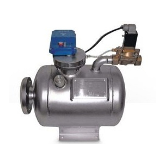
Page 10: Product Overview And Description
Installation and operation manual 2.3. Product overview and description Condensate inlet Manual condensate drain Venting line LED Valve Control elements / electric control LED Alarm Solenoid valve LED Power Condensate discharge solenoid valve TEST button Type plate NOTE No permanent draining Do not use the TEST button for permanent draining. -
Page 11: Function
Installation and operation manual 2.4. Function Illustration Description / Explanation Condensate flows through the condensate inlet and collects in the container (1). The container can fill completely, since pressure compensation takes place via the venting line (2). A capacitive double sensor (3) permanently records the filling level. -
Page 12: Dimensions
Installation and operation manual 2.5. Dimensions 2.5.1. BEKOMAT ® G1-i 68,3 (2.7) Flansch/flange G¾-i C 50 x 60,3 DIN 1092-1 30° G¾-i 237(9.3) 150 (5.9) Ø 11 486 (19.1) 2.5.2. BEKOMAT ® G2-i 68,3 (2.7) Flansch/flange G¾-i C 50 x 60,3 DIN 1092-1 25°... -
Page 13: Technical Data
Installation and operation manual 2.6. Technical data General data BM 8 BM 9 Min./max. storage/transport temperature +1 … +60 °C Min./max media/ambient temperature +1 … +60 °C Min./max operating overpressure 0.5 … 10 bar 0.5 … 4 bar Condensate inlet Fl. -
Page 14: Assembly
Installation and operation manual 3. Assembly 3.1. Warning notices DANGER Insufficient qualification, explosion Inappropriate handling due to insufficient qualification can lead to explosions, serious property damage and personal injuries or death. • All the tasks described in this installation and operation manual may only be carried out by skilled technical personnel¹... -
Page 15: Installation Steps
Installation and operation manual 3.2. Installation steps The following illustrations show possible assembly of the BEKOMAT 8/9. ® NOTE Assembly instructions • Install a separate BEKOMAT at each point where condensate occurs. ® • Do not use any tapered threaded joints. •... -
Page 16: Electrical Installation
Installation and operation manual 4. Electrical installation 4.1. Installation instructions DANGER Insufficient qualification Inappropriate handling due to insufficient qualification can lead to serious property damage and personal injuries or death. • All the tasks described in this installation and operation manual may only be carried out by skilled technical personnel¹... - Page 17 Installation and operation manual Netzteil Oscillator Power supply Netzanschluss Power Gehäuse Housing Sensor Sensor-Kreis Zeitauswertung Ventilsteuerung Magnetventil Sensor loop Time analysis Valve control Solenoid valve Alarmkontakt Alarm contact Alarmkontrolle Alarm monitoring Mains connection: • Route the cable through the screwed cable gland and connect to terminals L1, N, PE Alarm tapping: There is a potential-free alarm relay (changeover) available to forward the alarm in the event of a malfunction: •...
-
Page 18: Operation
Installation and operation manual 5. Operation The following displays show the different system states of the BEKOMAT ® Normal state: Normal operation: • Green LED “Power” lights up: Voltage OK, BEKOMAT in operation ® Fault state: • Yellow LED “Valve” lights up: Filling level reached ... -
Page 19: Functional Test
Installation and operation manual 5.1. Functional test Check normal function To check the solenoid valve, press the TEST button briefly (approx. 2 sec.). Red LED “Alarm” flashes, yellow LED “Valve” lights up Valve opens for condensate discharge Test fault signal To test the solenoid valve, shut off the condensate inlet and press the TEST button for approx. -
Page 20: Maintenance And Servicing
Inappropriate handling due to insufficient qualification can lead to serious property damage and personal injuries or death. • Maintenance work may only be carried out by trained service personnel from BEKO TECHNOLOGIES GmbH or authorised partners. Recommendation: Annually Respective set of wear parts: BEKOMAT ®... -
Page 21: Cleaning
Installation and operation manual 6.2. Cleaning The BEKOMAT is cleaned with a damp (not wet) cotton or disposable cloth as well as mild, commercially available ® detergent / soap. Spray a little detergent onto the clean cotton cloth or disposable cloth and carefully wipe the component. Then dry using a clean cloth or let it dry at room temperature. -
Page 22: Spare Parts
Installation and operation manual 6.3. Spare parts BEKOMAT ® 230 VAC 2000450 Set of wear parts 1 x solenoid valve, complete BEKOMAT ® 2 x hose connector 230 VAC 4005382 1 x hose section Other voltages on request Set of seals 8 x seal in sensor area BEKOMAT ®... -
Page 23: Troubleshooting
If your device has come into contact with pollutants, a decontamination declaration is also required. You will find corresponding templates on our website at www.beko-technologies.com. If you should return your device without a decontamination declaration and our Service department has doubts about the medium used, repairs will only be started once a respective declaration has been received. -
Page 24: Declaration Of Conformity
Installation and operation manual 8. Declaration of Conformity BEKOMAT ®... - Page 25 Installation and operation manual BEKO TECHNOLOGIES GMBH Im Taubental 7 41468 Neuss GERMANY Phone: +49 2131 988-0 www.beko-technologies.com EU Declaration of Conformity We hereby declare that the products named below comply with the stipulations of the relevant directives and technical standards. This declaration only refers to products in the condition in which they have been placed into circulation.
- Page 26 Installation and operation manual BEKOMAT ®...
- Page 27 Installation and operation manual BEKOMAT ®...
- Page 28 Tel. +81 44 328 76 01 service.it@beko-technologies.com info@beko-technologies.jp BEKO TECHNOLOGIES S. de R.L. de C. BEKO TECHNOLOGIES CORP. BEKO Technologies, S de R.L. de C.V. 900 Great Southwest Pkwy SW Blvd. Vito Alessio Robles 4602 Bodega 10 US - Atlanta, GA 30336 Zona Industrial Tel.
Need help?
Do you have a question about the BEKOMAT 8 and is the answer not in the manual?
Questions and answers