Table of Contents
Advertisement
Quality Assurance
Certificate Reg. No:
04 100 950420
Subject to change without notice
Manufacturer's Name: Saudi Airconditioning Manufacturing Co. Ltd.
Country of origin : Jeddah, Saudi Arabia
Nearest port of embarkation: Jeddah Islamic port
Product classification: Commercial and Residential
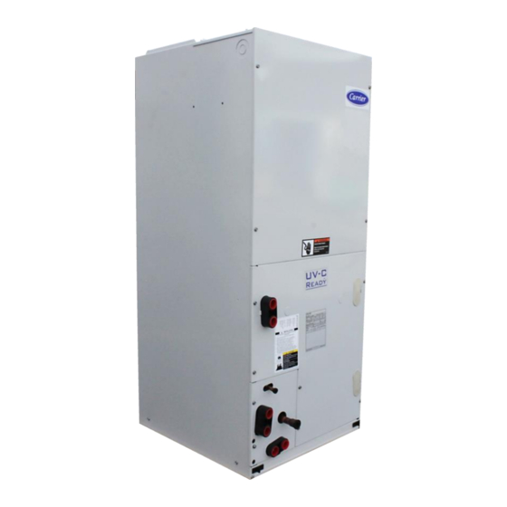
FB4P Direct Expansion multipoise fan coil units are available in 6 sizes with nominal cooling capacity range from 1.5 to
5.0 Tons. Each unit is designed to occupy a minimum space. No complex system controls are required for Carrier fan
coil units. Piping, drain, and wiring connections are readily accessible and mounting holes and slots are predrilled to
save installation time and field labor expense. They are compact and ready to fit where needed in the basement,
crawlspace, attic, utility room, or closet.
Contact your local Carrier representative for additional reference materials and information. www.carrier.com
FB4P – 50Hz
Nominal Cooling Capacity 1.5 – 5.0 Tons
HFC R -410A Refrigerant
Page 1 of 20
FB4P Fan Coil Units – 50Hz
Installation Operation Maintenance Manual
Advertisement
Table of Contents
Troubleshooting

Related Manuals for Carrier FB4P


Summary of Contents for Carrier FB4P
- Page 1 HFC R -410A Refrigerant FB4P Direct Expansion multipoise fan coil units are available in 6 sizes with nominal cooling capacity range from 1.5 to 5.0 Tons. Each unit is designed to occupy a minimum space. No complex system controls are required for Carrier fan coil units.
-
Page 2: Table Of Contents
Warranty is based on the general terms and conditions of the manufacturer. Any modifications to the design and/or installation made without discussion with Carrier and without advance written agreement will result in the loss of the right to any warranty claims and any claim for injury to personnel as a result of these modifications. -
Page 3: Physical Data / Electrical Data / Combination Matrix
Physical Data - FB4P Series Unit Model Unit size (Tons) Motor HP Evaporator Coil Coil Material (HP Tube) 3/8" Dia. Copper Tube Aluminum Coil Material (Finplate) 3 / 14.5 Rows / Fins Per Inch 2 / 14.5 3 / 14.5... -
Page 4: Unit Dimensional Drawing
Unit Dimensional Drawing Unit Coil Size Type Slope 42-11/16 1084.3 14-5/16 363.5 12-7/16 316.0 12-5/16 312.7 10-7/16 265.1 Slope 42-11/16 1084.3 14-5/16 363.5 12-7/16 316.0 12-5/16 312.7 10-7/16 265.1 Slope 47-11/16 1211.5 17-5/8 447.5 15-3/4 400.1 15-5/8 396.9 15-3/8 390.5 Slope 49-5/8 1260.5... -
Page 5: Introduction / Installation
NEC (National Electrical Code) and local codes. Receiving FB4P fan coil units are shipped individually packed in carton boxes. When cartons are individually off loaded from the truck, do not roll, nor throw, or drop the carton to avoid damage to the contents. Store boxes upright as the symbols on the boxes indicated. - Page 6 Mount Unit Unit can stand or lie on floor, or hang from ceiling or wall. Allow space for wiring, piping and servicing unit. Important: When unit is installed over a finished ceiling and/or living area, building codes may require a field- supplied secondary condensate pan installed.
- Page 7 Horizontal Right Conversion of Units with Slope Coils 1. Remove blower and coil access panels and fitting panel. (See Fig. 4.) 2. Remove coil mounting screw securing coil assembly to right-side casing flange. 3. Remove coil assembly. 4. Lay fan coil unit on its right side and reinstall coil assembly with condensate pan down. (See Fig. 4.) 5.
- Page 8 Fig - 3 Removal of Brackets on Modular Unit Fig - 4 Conversion for Horizontal Right Applications Using a Slope Coil Page 8 of 20...
- Page 9 Fig - 5 Conversion for Horizontal Right Applications Using A-Coil Air Ducts Connect the supply-air duct over the outside of the 3/4-in. flanges provided on the supply-air opening. Secure the duct to the flange, using proper fasteners for the type of duct used, and seal the duct-to-unit joint. If return-air flanges are required, install factory-authorized accessory kit.
- Page 10 1. The control kit is factory supplied, no thermostat required. 2. The wall mounted wired room controller can control all system functions without wireless remote control. 3. Standard wire length for the control board is 15 m. If extension is required, please contact your local carrier dealer.
- Page 11 Fig – 8 Condensate Drain Fig – 9 Insufficient Condensate Trap CAUTION Braze with Sil-Fos or Phos-copper on copper to copper joints and wrap a wet cloth around rear of fitting. Refrigerant Flow-Control Device Replace piston if required. Check piston size shown on indoor unit rating plate to see if it matches required piston shown on outdoor unit rating plate.
-
Page 12: Controller For Ducted Fan Coil Units
Controller For Ducted Fan Coil Units Features The controller is used to control (DX/CW) cooled ducted split unit, supports the following functions: - Modes: Cool, Dry, Fan, Heat | Indoor fan speed: Auto, High, Medium, Low - Sleep mode, Programmable On/Off timer - Compressor protections: Compressor 3 minutes restart protection, indoor coil anti-freeze, room sensor and indoor coil sensor failure monitoring - Random restart to minimize voltage dip during compressor first cut in cycle upon power up. - Page 13 Dry Mode: The fan speed runs automatically at low speed and compressor stopping and running is controlled by the difference between room and setting temperatures and by continuous running time. If indoor fan is programed to be turned off with comp signal, it will turn off once comp is cut off, In Dry mode, the humidity is reduced in the space to be air-conditioned.
-
Page 14: Ecm Motor Troubleshooting
ECM Motor Troubleshooting CAUTION It is recommended that the electrical connections on the ECM be facing down or between the 4 and 8 oclock position, and a drip loop formed out of the wiring harness leaving the motor Fig – 12 Drip Loop If the motor is running: but the system is noisy, shutting down on its limits or safeties or the evaporator coil is freezing, there is a good chance the motor is good. -
Page 15: Start-Up / Application And Accessories / Care And Maintenance
Application and Accessories Model FB4P are designed for flexibility and can be used for upflow, horizontal and downflow (kit required) applications. Factory authorized electric heater packages are available, see product data literature for available accessory kits. -
Page 16: Typical Wiring Schematic
Check Drain Lock open and tag unit electrical service switch. Check drain pan, drain line and trap at start of each cooling season. A standard type pipe cleaner for 3/4-in. ID pipe can be used to ensure that pipe is clear of obstruction so that condensate is carried away. -
Page 17: R-410A Refrigerant Quick Reference Guide
ATTENTION INSTALLERS AND SERVICE TECHNICIANS! R-410A Refrigerant Quick Reference Guide • R-410A refrigerant operates at 50-70 percent higher pressures than R-22. Be sure that servicing equipment and replacement components are designed to operate with R-410A refrigerant. • R-410A refrigerant cylinders are rose colored. •... -
Page 18: Air Conditioner Troubleshooting Chart
Air Conditioner Troubleshooting Chart NO COOLING OR INSUFFICIENT COOLING COMPRESSOR COMPRESSOR RUNS BUT RUNS BUT COMPRESSOR CYCLES ON INSUFFICIENT WILL NOT RUN INTERNAL COOLING OVERLOAD OUTDOOR FAN HIGH SUCTION HIGH SUCTION STOPPED OR CONTACTOR CONTACTOR LOOSE LEAD LOW SUCTION LOW HEAD OPEN CLOSED CYCLING ON... -
Page 19: Mandatory Startup Checklist And Record
This page is a mandatory checklist & record – the check to be executed and data to be recorded for future reference incase of failure. A copy of this checklist data has to be submitted to carrier representative. Completion of this checklist is a must for any field claim, no field support will be provided for incomplete or blank checklists. - Page 20 Manufacturer reserves the rights to discontinue or change at any time, specifications or designs without notice and without incurring any obligations. Page 20 of 20 Supersedes Version: FB4P-50HZ-IOM09 Catalog Number: FB4P-50HZ-IOM10 Effective Date: 26-10-2020 Phase: 50Hz...
Need help?
Do you have a question about the FB4P and is the answer not in the manual?
Questions and answers