Carrier FB4C Installation Instructions Manual
Fan coil units
Hide thumbs
Also See for FB4C:
- Installation manual ,
- Service and maintenance instructions (33 pages) ,
- Installation instructions manual (15 pages)
Table of Contents
Advertisement
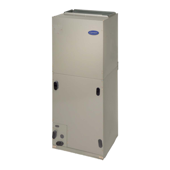
FB4C
NOTE: Read the entire instruction manual before starting the
installation.
TABLE OF CONTENTS
. . . . . . . . . . . . . . . . . . . . . . . . . . . . . . . . . .
. . . . . . . . . . . . . . . . . . . . . . . . . . . . . .
. . . . . . . . . . . . . . . . . . . . . . . . . . . . . . . . . . .
. . . . . . . . . . . . . . . . . . . . . . . . . . . . . .
. . . . . . . . . . . . . . . . . . . . . . . . . . . . . . .
. . . . . . . . . . . . . . . . . . . . . . . . . . . . . .
SAFETY CONSIDERATIONS
Improper installation, adjustment, alteration, service, maintenance,
or use can cause explosion, fire, electrical shock, or other
conditions which may cause death, personal injury or property
damage. Consult a qualified installer, service agency, or your
distributor or branch for information or assistance. The qualified
installer or agency must use factory- -authorized kits or accessories
when modifying this product. Refer to the individual instructions
packaged with kits or accessories when installing.
Follow all safety codes. Wear safety glasses, protective clothing
and work gloves. Have a fire extinguisher available. Read these
instructions thoroughly and follow all warnings or cautions
included in literature and attached to the unit. Consult local
building codes and the current editions of the National Electrical
Code (NEC) NFPA 70.
In Canada, refer to the current editions of the Canadian Electrical
Code CSA C22.1.
Recognize safety information. This is the safety- -alert symbol
When you see this symbol on the unit and in instruction manuals,
be alert to the potential for personal injury.
Understand the signal words DANGER, WARNING, and
CAUTION. These words are used with the safety- -alert symbol.
DANGER identifies the most serious hazards which will result in
severe personal injury or death. WARNING signifies hazards
Installation Instructions
PAGE
. . . . . . . . . . . . . . . . . . . . . . . .
. . . . . . . . . . . . . . . . . . . . . . . . .
. . . . . . . . . . . . . . . . . . . . .
. . . . . . . . . . . . .
. . . . . . . . . . . . . . . . . . . . . . . .
. . . . . . . . . . . . . . . . . . . . .
. . . . . . . . . . . . . . . . . . . . . . . . . .
. . . . . . . . . . . . . . . . . . . . . . . .
. . . . . . . . . . . . . . . .
which could result in personal injury or death. CAUTION is used
to identify unsafe practices which may result in minor personal
injury or product and property damage. NOTE is used to highlight
suggestions which will result in enhanced installation, reliability, or
operation.
1
!
1
2
ELECTRICAL OPERATION HAZARD
2
Failure to follow this warning could result in personal injury
2
or death.
2
Before installing or servicing unit, always turn off all power to
unit. There may be more than one disconnect switch. Turn off
4
accessory heater power if applicable. Lock out and tag switch
4
with a suitable warning label.
. .
7
7
!
8
9
CUT HAZARD
9
Failure to follow this caution may result in personal injury.
9
Sheet metal parts may have sharp edges or burrs. Use care and
9
wear appropriate protective clothing and gloves when
handling parts.
10
FB4C models are R- -410A Fan Coils designed for installation
flexibility. These units are designed to meet the low air leak
requirements currently in effect.
FB4CNF(018- -048) uses a refrigerant piston metering device. A
TXV is used on FB4CNP(018- -061). All FB4C fan coils use a
multi- -tap ECM motor for efficiency. These units have be designed
for upflow, downflow (kit required), and horizontal orientations,
including manufactured and mobile home applications.
These units require a field supplied air filter, and are designed
specifically for R- -410A refrigerant air conditioners and heat
pumps as shipped. These units are available for systems of 18,000
through 60,000 BTUh nominal cooling capacity. Factory- -
authorized, field - - installed electric heater packages are available in
sizes 5 through 30kW. See Product Data literature for all available
accessory kits.
.
FAN COIL UNITS
FOR R- -410A REFRIGERANT
SIZES 018 TO 061
WARNING
CAUTION
INTRODUCTION
Advertisement
Table of Contents

Related Manuals for Carrier FB4C


Summary of Contents for Carrier FB4C
-
Page 1: Table Of Contents
FB4CNF(018- -048) uses a refrigerant piston metering device. A when modifying this product. Refer to the individual instructions TXV is used on FB4CNP(018- -061). All FB4C fan coils use a packaged with kits or accessories when installing. multi- -tap ECM motor for efficiency. These units have be designed for upflow, downflow (kit required), and horizontal orientations, Follow all safety codes. -
Page 2: Heater Packages
HEATER PACKAGES Use fireproof resilient gasket, 1/8 to 1/4- -in (3 to 6 mm) thick, between duct, unit, and floor. This unit may or may not be equipped with an electric heater package. For units not equipped with factory- -installed heat, a CAUTION factory- -approved, field- -installed, UL listed heater package is available from your equipment supplier. - Page 3 COIL MOUNTING BLOWER SCREW ASSEMBLY COIL FA CT OR Y SHIPPED BRACKET HORIZONTAL LEFT APPLICATION COI L SUPPORT RAIL COIL SUPPORT DRAIN PA N RAIL SUPPORT BRACKET COIL BRACKET SLOPE COIL HORIZONTAL DRAIN PAN PRIMARY DRAIN DRAINPAN PRIMARY DRAIN REFRIGERANT HORIZONTAL LEFT AIR SEAL CONNECTIONS...
-
Page 4: Step 3 - Air Ducts
Step 4 — Electrical Connections air leaks and cabinet sweating. FB4C units from the factory protect the low voltage circuit with a 3 D. Manufactured and Mobile Home Housing Applications amp automotive type fuse in- -line on the wire harness and Does 1. - Page 5 WARNING FAN COIL THERMOSTAT (CONTROL) ELECTRICAL SHOCK HAZARD Failure to follow this warning could result in personal injury or death. Field wires on the line side of the disconnect found in the fan coil unit remain live, even when the pull- -out is removed. Service and maintenance to incoming wiring cannot be performed until the main disconnect switch (remote to the AIR COND.
- Page 6 Heater Staging FAN COIL HEAT PUMP THERMOSTAT (CONTROL) (CONTROL) CAUTION PROPERTY DAMAGE HAZARD Failure to follow this caution may result in product or property damage. If W2, W3, and E on any 3 stage heater (18, 20, 24, or ODTS1 30kW) are individually connected as with outdoor thermostats or any other situation, emergency heat relay must ODTS2...
-
Page 7: Step 5 - Refrigerant Tubing Connection And Evacuation
DISTRIBUTOR HEX NUT TEFLON SEAL A11048 TEFLON RING Fig. 16 - - Motor Speed Selection for FB4C Only Step 5 — Refrigerant Tubing Connection and Evacuation PISTON Use accessory tubing package or field- -supplied tubing of refrigerant grade. Suction tube must be insulated. Do not use... -
Page 8: Step 7 - Condensate Drains
CAUTION PRODUCT OPERATION HAZARD Failure to follow this caution may result in improper product operation. FILTER ACCESS PANEL If using a TXV in conjunction with a single- -phase SECONDARY DRAIN WITH reciprocating compressor, a compressor start capacitor and APPROPRIATE TRAP REQUIRED (USE FACTORY KIT OR relay are required. -
Page 9: Step 9 - Sequence Of Operation
Step 9 — Sequence of Operation FAN COIL THERMOSTAT (CONTROL) A. Continuous Fan Thermostat closes R to G. G energizes fan relay on PCB which completes circuit to indoor blower motor. When G is de- -energized, there is a 90- -sec delay before relay opens. B. -
Page 10: Airflow Performance Tables
1. Airflow based upon dry coil at 230v with factory- -approved filter and electric heater (2 element heater sizes 018 through 036, 3 element heater sizes 042 through 061). For FB4C models, airflow at 208 volts is approximately the same as 230 volts because the multi- -tap ECM motor is a constant torque motor. - Page 11 AIRFLOW PERFORMANCE TABLES (cont.) Table 2 – FB4C Air Delivery Performance Correction Component Pressure Drop (in. wc) at Indicated Airflow (Dry to Wet Coil) 1000 1100 1200 1300 1400 1500 1600 1700 1800 1900 2000 UNIT SIZE 0.034 0.049 0.063 0.034...
- Page 12 R- -410A QUICK REFERENCE GUIDE R- -410A refrigerant operates at 50- -70 percent higher pressures than R- -22. Be sure that servicing equipment and replacement components are designed to operate with R- -410A refrigerant. R- -410A refrigerant cylinders are rose colored. Recovery cylinder service pressure rating must be 400 psig, DOT 4BA400 or DOT BW400.
Need help?
Do you have a question about the FB4C and is the answer not in the manual?
Questions and answers