Table of Contents
Advertisement
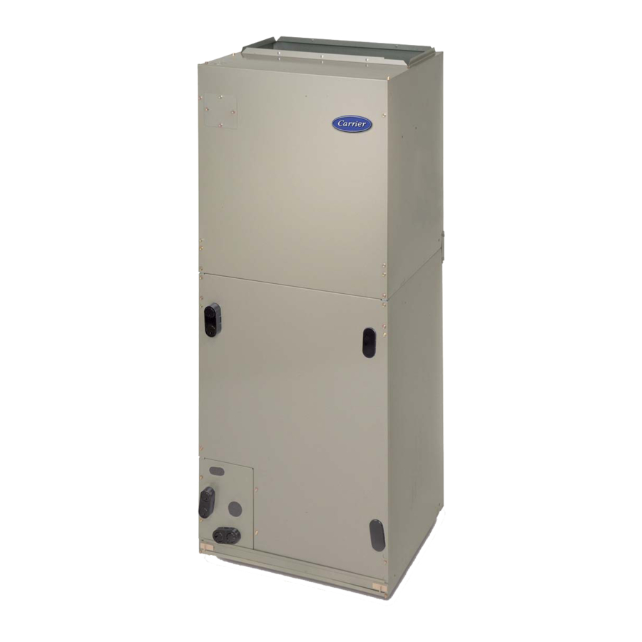
FV4C
002, 003, 005, 006
Fig. 1 - - Model FV4C
NOTE: Read the entire instruction manual before starting the
Installation Instructions
A02332
Fan Coil for Puronr Refrigerant
SAFETY CONSIDERATIONS
Improper installation, adjustment, alteration, service, maintenance,
or use can cause explosion, fire, electrical shock, or other
conditions which may cause death, personal injury or property
damage. Consult a qualified installer, service agency, or your
distributor or branch for information or assistance. The qualified
installer or agency must use factory- -authorized kits or accessories
when modifying this product. Refer to the individual instructions
packaged with the kits or accessories when installing.
Follow all safety codes. Wear safety glasses, protective clothing,
and work gloves. Use quenching cloth for brazing operations.
Have fire extinguisher available. Read these instructions
thoroughly and follow all warning or cautions included in literature
and attached to the unit. Consult local building codes and the
current editions of the National Electrical Code (NEC) NFPA 70.
In Canada, refer to the current editions of the Canadian Electrical
Code CSA C22.1.
Recognize safety information. When you see this symbol
the unit and in instructions or manuals, be alert to the potential for
personal injury. Understand the signal words DANGER,
WARNING, CAUTION, and NOTE. These words are used with
the safety- -alert symbol. DANGER identifies the most serious
hazards which will result in severe personal injury or death.
WARNING signifies hazards which could result in personal injury
or death. CAUTION is used to identify unsafe practices which
may result in minor personal injury or product and property
damage. NOTE is used to highlight suggestions which will result
in enhanced installation, reliability, or operation.
WARNING
!
Failure to follow this warning could result in personal injury
or death.
Before installing or servicing system, always turn off main
power to system. There may be more than one disconnect
switch. Tag disconnect switch with a suitable warning label.
Turn off accessory heater power if applicable.
!
Failure to follow this caution may result in personal injury.
Sheet metal parts may have sharp edges or burrs. Use care and
wear appropriate protective clothing and gloves when
handling parts.
CAUTION
on
Advertisement
Table of Contents

Related Manuals for Carrier FV4C


Summary of Contents for Carrier FV4C
-
Page 1: Installation Instructions
There may be more than one disconnect switch. Tag disconnect switch with a suitable warning label. A02332 Turn off accessory heater power if applicable. Fig. 1 - - Model FV4C NOTE: Read the entire instruction manual before starting the CAUTION installation. - Page 2 INTRODUCTION Procedure 2 — MOUNT FAN COIL Model FV4C Fan Coil units are designed for flexibility and can be Unit can stand or lie on floor, or hang from ceiling or wall. Allow used for upflow, horizontal, or downflow (kits required on space for wiring, piping, and servicing unit.
- Page 3 A-COIL HORIZONTAL LEFT PRIMARY SECONDARY DRAIN FIELD DRAIN SUPPLIED HANGING STRAPS FRONT SERVICE CLEARANCE (Full face of unit) UNIT 002-005 21" (533 mm) 006 24" (610 mm) LOW VOLT ENTRY OPTIONS 1 3 /4" (44 mm) FILTER ACCESS CLEARANCE PRIMARY DRAIN SECONDARY DRAIN...
- Page 4 B. Modular Units C. Horizontal Installations The FV4C Fan Coil in sizes 003, 005 and 006 are available in Be sure installation complies with all applicable building codes that 2- -piece modular construction. Modular construction allows may require installation of a secondary condensate pan.
- Page 5 REFRIGERANT AIR SEAL CONNECTIONS ASSEMBLY HORIZONTAL RIGHT APPLICATION COIL SUPPORT RAIL COIL BRACKET DRAIN PAN SUPPORT BRACKET COIL SUPPORT RAIL COIL BRACKET HORIZONTAL DRAIN PAN PRIMARY DRAIN HORIZONTAL RIGHT SECONDARY DRAIN HORIZONTAL RIGHT A00071 Fig. 7 - - A- -Coil in Horizontal- -Right Application E.
- Page 6 1/8- - to 1/4- -in. (3.2 to 6.4mm) thick, between duct, unit, Duct connection flanges are provided on unit air discharge connection. When using FV4C units with 20- -, 24- -, and 30- -kW and floor. electric heaters, maintain a 1- -in. (25mm) clearance from...
- Page 7 W/W1 OUTDOOR SENSOR OUTDOOR SENSOR COOL STAGE 1 Y/Y2 Y/Y2 CONNECTION A98475 Fig. 11 - - FV4C Fan Coil Wiring with 1- -Speed Heat Pump 24 VAC HOT REMOVE J1 JUMPER DEHUMIDIFY MODES DHUM DEHUMIDIFY 24 VAC COMM HUMIDIFY HUMIDIFIER...
- Page 8 Intelligent Heat staging of the electric heat package is possible connection uses reducing washers, a separate ground wire when the FV4C is installed as a part of a single- -speed heat pump must be used. system using a corporate 2- -speed programmable thermostat ,...
- Page 9 CAUTION CAUTION PRODUCT DAMAGE HAZARD PROPERTY DAMAGE HAZARD Failure to follow this caution may result in product or property Failure to follow this caution may result in product or property damage. damage. Wrap a wet cloth around rear of fitting to prevent damage to Shallow running traps are inadequate and DO NOT allow proper TXV and factory- -made joints.
- Page 10 Fig. 18 - - Detail of FV4C Printed- -Circuit Board instructions and refrigerant charging method details. Procedure 8 — EASY SELECT The FV4C Fan Coil must be configured to operate properly with CONFIGURATION TAPS system components with which it is installed. To successfully configure a basic system (see information printed on circuit board Easy Selectt taps are used by the installer to configure a system.
- Page 11 350 CFM per ton. The factory setting Guide) is AC. (See Fig. 17, C as indicated.) The FV4C Fan Coil provides better than average humidity control D. AC/HP CFM ADJUST - - Select Medium, Low, or High and heated air temperature. This configuration will improve the...
- Page 12 When using an electronic air cleaner with the FV4C Fan Coil, use Airflow Sensor Part No. The FV4C will supply airflow in a range which is more than twice KEAAC0101AAA. The airflow sensor turns on electronic air the range of a standard fan coil.
- Page 13 the full cooling or cooling plus dehumidify mode requested value. C. Use following procedure to check control signals: If circuit R to G is open (0 vac) for super dehumidify mode, the THERMOSTAT motor delivers reduced airflow to maximize the humidity removal 1.
- Page 14 Disconnect all electrical power to unit before performing any maintenance or service on it. Table 2 – CFM Range for FV4C Units FAN COIL SIZE SYSTEM SIZES CFM RANGE...
- Page 15 2. Air flow can be adjusted +15% or ---10% by selecting HI or LO respectively for all modes except fan only. 3. Dry coil at 230 volts and with 10KW heater and filter installed. 4. Airflows shown are at standard air conditions. Table 4 – FV4C Fan Coil Airflow Delivery (CFM) in Heat Pump Only Heating Mode OPERATING MODE SINGLE—SPEED TWO—SPEED APPLICATION...
- Page 16 1810 2085 NOTE: Lo, NOM, and HI refer to AC, HP CFM ADJUST selection. --- Airflow not recommended for heater/system size. Table 6 – FV4C Minimum CFM for Electric Heater Application HEAT PUMP HEATER SIZE kW FAN COIL UNIT UNIT SIZE...
- Page 17 Table 7 – Wiring connection of FV Fan Coil Wiring Harness 16---IN PLUG ON WIRING HARNESS TO MOTOR WIRING HARNESS CONNECTION TO EASY SELECT BOARD Pin on Signal on Pin with Pin on 12---Pin Plug or 16---Pin Screw Terminal Description Wire Color Set---up Selection Plug...
- Page 18 Catalog No: IM---FV4C ---01 Copyright 2009 CAC / BDP D 7310 W. Morris St. D Indianapolis, IN 46231 Printed in U.S.A. Edition Date: 05/09 Manufacturer reserves the right to change, at any time, specifications and designs without notice and without obligations.
Need help?
Do you have a question about the FV4C and is the answer not in the manual?
Questions and answers