Table of Contents
Advertisement
Quality Assurance
Certificate Reg. No:
04 100 950420
Subject to change without notice
Manufacturer's Name: Saudi Airconditioning Manufacturing Co. Ltd.
Country of origin : Jeddah, Saudi Arabia
Nearest port of embarkation: Jeddah Islamic port
Product classification: Commercial and Residential
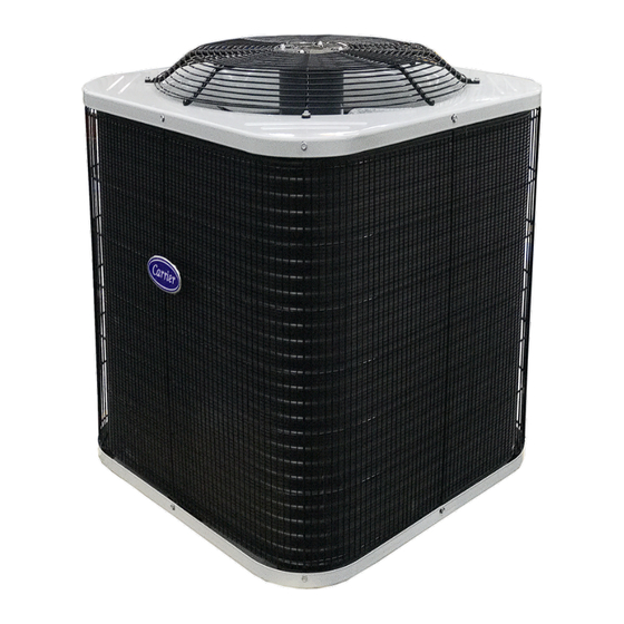
The 38C series energy efficient split top discharge condensing units incorporate innovative technology to provide
reliable summer cooling performance. The units are pre-wired, pre-charged with Puron® R-410A refrigerant, and
tested at the factory, designed to occupy a minimal space. These units are matched with Carrier direct expansion fan
coil units that provides economical performance now and in the future.
Contact your local Carrier representative for additional support.
38C Top Discharge Condensing Units – 50Hz
38C – 50Hz
Nominal Cooling Capacity 1.5 – 5.0 Tons
HFC R -410A Refrigerant
Page 1
Installation, Operation and Maintenance Manual
Advertisement
Table of Contents

Related Manuals for Carrier 38C Series


Summary of Contents for Carrier 38C Series
- Page 1 The units are pre-wired, pre-charged with Puron® R-410A refrigerant, and tested at the factory, designed to occupy a minimal space. These units are matched with Carrier direct expansion fan coil units that provides economical performance now and in the future.
-
Page 2: Table Of Contents
Warranty is based on the general terms and conditions of the manufacturer. Any modifications to the design and/or installation made without discussion with Carrier and without advance written agreement will result in the loss of the right to any warranty claims and any claim for injury to personnel as a result of these modifications. -
Page 3: Physical Data
Physical Data 38C Model 36-1Ph 36-3Ph Unit Size (Tons) 62.0 Unit Operating Weight Cool Only (kg) 81.9 86.5 87.5 86.1 91.1 100.9 Grey Enamel Finish Unit Color Maximum Cooling Ambient (°F) Minimum Cooling Ambient (°F) Sound Power (dBA) 68.8 70.5 72.0 74.0 74.0... -
Page 4: Base Unit Dimensions
Base Unit Dimensions Notes: 1. Allow 762.0 clearances to service side of unit, 1219.2 above unit, 152.4 on one side, 304.8 on remaining side and 609.6 between units for proper air flow. 2. Center of gravity 3. All dimensions are in "mm" unless noted. Model Size 587.4 722.3... -
Page 5: Combination Matrix And Ratings / Electrical Data
Combination Matrix and Ratings Capacity (Btu/hr) EER (Btu/hr) / W Power Input (kW) kWh/Yr AMPS Indoor Outdoor Model Indoor Model Voltage Type 38CKPC18DS70 42TPM018-71 230/1/50 Ducted 18,800 16,500 11.8 1.593 1.833 4,301 1,833 38CKPC24DS70 42TPM024-71 230/1/50 Ducted 25,000 21,500 11.8 2.119 2.443 5,721... -
Page 6: Typical Wiring Schematic
Typical Wiring Schematic 38CKP18-24-30-36 (230V/240V-1PH-50Hz) - Ducted 38CKP36-42-48-60 (400V/415V-3PH-50Hz) - Ducted Page 6... - Page 7 Typical Wiring Schematic (Continued) 38CKP36-42-48-60 (400V/415V-3PH-50Hz) – Ducted With Capacitor Bank Page 7...
-
Page 8: Installation / Startup / Service / Maintenance
Installation Un-Packing Instructions 1. Prepare unit for unpacking at site of final installation. 2. Remove two (2) pcs. Plastic straps. 3. Open carton flaps and remove top pad then lift carton box. 4. Remove unit from wood pallet and install according to installation procedures. Fig.1 Un-packing Instructions Packing Instructions 1. - Page 9 Fig. 3 Connecting Tubing Installation Step 1 — Complete Pre-Installation Checks Unpack Unit—Move unit to final location. Follow unpacking instructions as shown in manual, being careful not to damage service valves or grilles. Inspect Shipment — File claim with shipping company if shipment is damaged or incomplete. Check unit nameplate to ensure unit matches job requirements.
- Page 10 Fig – 4: Lifting Unit Fig – 5: Rooftop/Ground Fig – 6: Tie Down With Sling Mounting Knockouts Base Pan Tie Down Knockouts (mm) Minimum Mounting Pad Dimensions (mm) Width x Dept (mm) 596.9 x 596.9 111.0 458.8 182.6 660 x 660 800.1 x 800.1 166.7 627.1...
- Page 11 Unit failure as a result of operation on improper line voltage or excessive phase imbalance constitutes abuse and may cause damage to electrical components. Such operation will invalidate any applicable Carrier warranty. Power Wiring — Unit is factory-wired for voltage shown on nameplate. Provide adequate, fused disconnect switch within sight of unit, readily accessible but out of reach of children.
- Page 12 2. Make certain field electrical power source agrees with unit nameplate and rating. 3. Open all service valves. Leak Test — Field piping and fan coil must be leak tested by pressure method described in Carrier Standard Service Techniques Manual, Chapter 1, Section 1-6.
- Page 13 (overloads may require up to 45 minutes to reset). When an internal overload is suspected of being open, check by using an ohmmeter or continuity tester. If necessary, refer to Carrier Standard Systems Techniques Manual, Chapter 2, for complete information.
- Page 14 Fan motors are waterproof. Warning Do not use harsh chemicals for cleaning coils, use only water, compressed air or Carrier approved coil cleaners. Leak Detection — New installations should be checked for leaks prior to complete charging. If a system has lost all or most of its charge, system must be pressurized again to approximately 150 lb minimum.
- Page 15 Assuming that a system is pressurized with either all refrigerant or a mixture of nitrogen and refrigerant, leaks in the system can be found with an electronic leak detector that is capable of detecting HFC refrigerant. If system has been operating for some time, make first check for a leak visually.
-
Page 16: Superheat Charging Table / Required Suction Tube Temperature
Superheat Charging Table EVAPORATOR ENTERING AIR (°C WB) OUTDOOR TEMP (°C) 11.1 11.9 12.8 14.4 10.0 10.8 11.7 13.3 – 10.6 11.7 – – 10.6 – – – – – – – – – – – – – – – –... -
Page 17: Pressure Vs. Temperature Chart R-410A
Pressure vs. Temperature Chart R-410A PSIG °F PSIG °F PSIG °F PSIG °F PSIG °F PSIG °F -37.7 37.8 74.3 100.2 120.7 137.6 -34.7 38.7 74.9 100.7 121.0 137.9 -32.0 39.5 75.5 101.1 121.4 138.3 -29.4 40.5 76.1 101.6 121.7 138.6 -36.9 41.3... -
Page 18: Required Liquid Line Temperature
Required Liquid Line Temperature REQUIRED SUBCOOLING TEMPERATURE (°F) LIQUID PRESSURE AT SERVICE VALVE (PSIG) Subcooling Charging Table Page 18... -
Page 19: R-410A Refrigerant Quick Reference Guide
ATTENTION INSTALLERS AND SERVICE TECHNICIANS! R-410A Refrigerant Quick Reference Guide • R-410A refrigerant operates at 50-70 percent higher pressures than R-22. Be sure that servicing equipment and replacement components are designed to operate with R-410A refrigerant. R-410A refrigerant cylinders are rose colored. •... -
Page 20: Air Conditioner Troubleshooting Chart
Air Conditioner Troubleshooting Chart NO COOLING OR INSUFFICIENT COOLING COMPRESSOR COMPRESSOR RUNS BUT RUNS BUT COMPRESSOR CYCLES ON INSUFFICIENT WILL NOT RUN INTERNAL COOLING OVERLOAD OUTDOOR FAN HIGH SUCTION HIGH SUCTION STOPPED OR CONTACTOR CONTACTOR LOOSE LEAD LOW SUCTION LOW HEAD OPEN CLOSED CYCLING ON... -
Page 21: Mandatory Startup Checklist And Record
This page is a mandatory checklist & record – the check to be executed and data to be recorded for future reference incase of failure. A copy of this checklist data has to be submitted to carrier representative. Completion of this checklist is a must for any field claim, no field support will be provided for incomplete or blank checklists. - Page 22 NOTES Page 22...
-
Page 23: Long Line Guideline
Appendix Long-Line Guideline. (Single Stage Application For 38C Only) A. Safety Considerations Only trained service technicians familiar with standard service instructions and training materials should attempt installation, service, and repair of these units. Improper installation, adjustment, alteration, service, maintenance, or use can cause explosion, fire, electrical shock, or other conditions which may cause death, personal injury, or property damage. - Page 24 C. Introduction An application is considered Long Line, when the refrigerant level in the system requires the use of accessories to maintain acceptable refrigerant management for systems reliability. See Table 1 for required accessories. Defining a system as long line depends on the liquid line diameter, actual length of the tubing, and vertical separation between the indoor and outdoor units.
- Page 25 Table 1 – Long Line Accessory Requirements OUTDOOR UNIT ABOVE OUTDOOR UNIT BELOW NO ELEVATION CHANGE ACCESSORY Liquid line solenoid (LLS) KHALS0401LLS KHALS0401LLS KHALS0401LLS at outdoor TXV on indoor (Standard on all 13 SEER platform indoor coils and fan coils) Crankcase heater (if not factory supplied) Start capacitor and relay...
- Page 26 F. Metering Device — Long Line Cooling In current equipment, all indoor units use a TXV with 15 to 30% bleed for metering in the cooling mode. This provides adequate refrigerant migration protection for all cooling applications. G. Piston Sizing — Heat Pumps Only An AccuRater (fixed orifice) is used for refrigerant metering in the heating mode.
- Page 27 Table 4 - Refrigerant Charge Adjustments Liquid Line Size Puron Charge (oz/ft) 0.60 (Factory charge for lineset = 13.5 oz (382.7) 5/16 0.40 0.27 Units are factory charged for 25 ft (7.6 m) of 3/8” liquid line. The factory charge for 3/8” lineset 9 oz (266.2 g). When using other length or diameter liquid lines, charge adjustments are required per the chart above.
- Page 28 Table 6 – AC / HP with Puron® Refrigerant Long Line Description ft (m) Beyond these lengths, long line accessories are required AC Liquid Line Size Units On Same Level No accessories needed within allowed lengths 5/16 120 (36.6) 80 (24.4) HP Liquid Line Size Units On Same Level 80 (24.4)
- Page 29 Fig. 4 – Outdoor Unit Above Indoor Unit • A TXV with 15 to 30% bleed must be installed at indoor unit when the application qualifies as long line. See Table 11. • A crankcase heater must be installed on compressor when the application qualifies as long line. See Table 11. •...
-
Page 30: General
J. General Requirements (Check List) All Long Line Applications • TXV with 15 to 30% bleed must be installed at indoor unit. • Hard Start Kit (start capacitor and relay) must be installed on outdoor unit. • Crankcase heater must be installed on compressor. •... - Page 31 Page 31...
- Page 32 Manufacturer reserves the rights to discontinue or change at any time, specifications or designs without notice and without incurring any obligations. Supersedes Version: 38C-50Hz-IOM-01 Catalog Number: 38C-50-EN-IOM-02 Page 32 Effective Date: 12-07-2017 Phase: 50Hz...
Need help?
Do you have a question about the 38C Series and is the answer not in the manual?
Questions and answers