Table of Contents
Advertisement
Installation and Start-Up Instructions
Direct Expansion
Fan Coil
001-006
NOTE: Read entire instruction manual before starting installation.
This symbol → indicates a change from the last publication.
Improper installation, adjustment, alteration, service, maintenance, or use can cause explosion, fire, electrical shock or other conditions which may
cause personal injury or property damage. Consult a qualified installer, service agency, or your distributor or branch for information or assistance.
The qualified installer or agency must use factory-authorized kits or accessories when modifying this product. Refer to the individual instructions
packaged with the kits or accessories when installing.
Follow all safety codes. Wear safety glasses and work gloves. Use quenching cloth for brazing operations. Have fire extinguisher available. Read
these instructions thoroughly and follow all warnings or cautions attached to the unit. Consult local building codes and National Electrical Code
(NEC) for special requirements.
Recognize safety information. This is the safety-alert symbol
to the potential for personal injury.
Understand the signal words DANGER, WARNING and CAUTION. These words are used with the safety-alert symbol. DANGER identifies the
most serious hazards which will result in severe personal injury or death. WARNING signifies hazards which could result in personal injury or
death. CAUTION is used to identify unsafe practices which would result in minor personal injury or product and property damage.
Model FK4C Fan Coil units are designed for flexibility and can be used for upflow, horizontal, or downflow applications.
These units are available for application in systems of 18,000 through 60,000 Btuh nominal cooling capacities. (See Fig. 2 and 3.)
Factory-authorized, field-installed electric heater packages are available in 5 through 30 kw. See Product Data for available accessory kits.
WARNING: Before installing or servicing fan coil, always turn off all power to unit. There may be more than 1
disconnect switch. Turn off accessory heater power if applicable. Electrical shock can cause personal injury or death.
Form: IM-FK4C-04
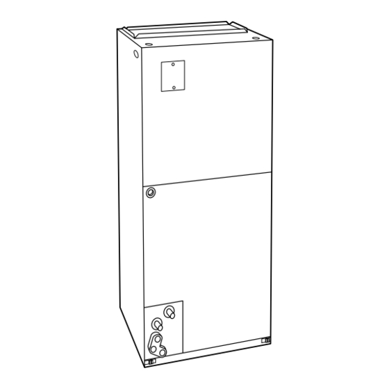
Fig. 1—Model FK4C
SAFETY CONSIDERATIONS
INTRODUCTION
Cancels: IM-FK4C-03
. When you see this symbol on the unit and in instructions or manuals, be alert
Printed in U.S.A.
10-97
FK4C
A95518
Catalog No. 63FK-4C0
Advertisement
Table of Contents

Related Manuals for Carrier FK4C


Summary of Contents for Carrier FK4C
- Page 1 INTRODUCTION Model FK4C Fan Coil units are designed for flexibility and can be used for upflow, horizontal, or downflow applications. These units are available for application in systems of 18,000 through 60,000 Btuh nominal cooling capacities. (See Fig. 2 and 3.) Factory-authorized, field-installed electric heater packages are available in 5 through 30 kw.
- Page 2 —2—...
- Page 3 —3—...
- Page 4 Only use return-air opening provided. All return air must pass through the coil. (See Fig. 4.) B. Modular Units The FK4C Fan Coil in size 006 is a 2-piece modular unit. Modular construction allows installer to disassemble unit into 2 components, coil box and blower box, for ease of installation. (See Fig. 5.) To disassemble unit, remove rear corner brackets by removing 2 screws which secure brackets.
- Page 5 BLOWER BOX 2 SCREWS 2 SCREWS REAR CORNER BRACKET 2 SCREWS COIL BOX A95293 Fig. 5—Modular Unit Assembly CAUTION: For optimum condensate drainage performance in horizontal installations, unit should be leveled along its length or raised 1/4 in. at the air inlet. The unit should also be pitched forward 1/4 in. to 1/2 in. toward the front condensate drains.
- Page 6 A-COIL HORIZONTAL LEFT PRIMARY SECONDARY DRAIN FIELD DRAIN SUPPLIED HANGING STRAPS 24-IN. FRONT SERVICE CLEARANCE (FULL FACE UNIT OF UNIT) LOW VOLT ENTRY OPTIONS 1 3 /4 IN. FILTER ACCESS CLEARANCE PRIMARY DRAIN SECONDARY DRAIN POWER ENTRY OPTIONS A95292 Fig. 6—Slope Coil in Horizontal-Left Application COIL MOUNTING BLOWER SCREW...
- Page 7 To convert units for downflow applications, refer to Installation Instructions supplied with kit for proper installation. For FK4C unit sizes 001 and 003, use kit Part No. KFADC0201SLP. For FK4C unit sizes 002, 005, and 006 use kit Part No. KFADC0401ACL. Use fireproof resilient gasket, 1/8- to 1/4-in.
- Page 8 C. Intelligent Heat Option Intelligent Heat staging of the electric heat package is possible when the FK4C is installed as a part of a single-speed heat pump system using a corporate 2-speed programmable thermostat (model TSTATXXP2S01-A) and any 1 of the following electric heat packages: KFAEH2501N09, KFAEH2601F15, KFAEH2801C15, KFAEH2701S15, KFAEH1001F24 or KFAEH1101F30.
- Page 9 PROCEDURE 5—FK4C FAN COIL SEQUENCE OF OPERATION The FK4C will supply airflow in a range which is more than twice the range of a standard fan coil. It is designed to provide nominal cooling capacities at a 50°F evaporator temperature and the required airflow which enables it to match with 4 air conditioner or heat pump system sizes.
- Page 10 Table 1–CFM Range for FK4C Units FAN COIL SIZE SYSTEM SIZES CFM RANGE FK4CNF001 018, 024, 030, 036 450-1275 FK4CNF002 018, 024, 030, 036 450-1275 FK4CNF003 024, 030, 036, 042 525-1475 FK4CNF005 030, 036, 042, 048 550-1700 FK4CNB006 036, 042, 048, 060 550-2150 A.
- Page 11 UNIT ″ ⁄ ″ ⁄ DO NOT USE SHALLOW RUNNING TRAPS! A95321 A95320 Fig. 13—Recommended Condensate Trap Fig. 14—Insufficient Condensate Trap Units have sweat suction and liquid tube connections. Make suction tube connection first. 1. Cut tubing to correct length. 2.
- Page 12 (See Fig. 16 and 17.) The FK4C Fan Coil must be configured to operate properly with system components with which it is installed. To successfully configure a basic system (see information printed on circuit board label located next to select pins), move the 6 select wires to the pins which match the components used.
- Page 13 If EAC relay is field supplied, use field supplied wiring, terminations and wire per the EAC wiring schematic. (See Fig. 19.) NOTE: If the FK4C is installed with an air conditioner and electric heat is the primary heating device, a thermostat which turns on the G output with a call for heat is required for air cleaning or humidification during heating mode.
- Page 14 D. Dehumidify Capability with Standard Humidistat Connection Latent capacities for systems using the FK4C Fan Coil are better than average systems. If increased latent capacity is an application requirement, the field wiring terminal block provides connection terminals for use of standard humidistat. The FK4C Fan Coil will detect humidistat contacts opening on increasing humidity and reduce its airflow to approximately 80 percent of nominal cooling mode airflow.
- Page 15 AUX HEAT KW/CFM 0-30 0-20 0-10 1075 AC/HP SIZE SYSTEM TYPE HP-COMFORT HP-EFF AC/HP CFM ADJUST ON/OFF DELAY 230 VAC OR FK4C 115 VAC BRANCH CKT AUX1 AUX2 CONTINUOUS FAN GND HOT NEUT AUX1 HUM1 AUX2 HUM2 CEBD430226-01B CESS430226-01B 24VAC...
- Page 16 Consult fan coil service manual available from equipment distributor for maintenance procedures. WARNING: As with any mechanical equipment, personal injury can result from sharp metal edges, etc, therefore, care should be taken when removing parts. Using Owner’s/User Manual furnished in outdoor unit, the installing technician should explain to the consumer system operation with particular emphasis on indoor fan coil operation sounds and filter maintenance.
Need help?
Do you have a question about the FK4C and is the answer not in the manual?
Questions and answers