Table of Contents
Advertisement
Quick Links
Advertisement
Table of Contents

Related Manuals for Dometic Go Power GP-ISW-200


Summary of Contents for Dometic Go Power GP-ISW-200
- Page 1 PURE SINE WAVE INVERTER User Manual GP-ISW-200/400 © 2021 Go Power! Worldwide Technical Support and Product Information gpelectric.com Go Power! | Dometic 201-710 Redbrick Street Victoria, BC, V8T 5J3 Tel: 1.866.247.6527 82654_MAN_ISW200-400_RevA...
- Page 2 Congratulations on purchasing your Go Power! GP-ISW Inverter. The unit is a highly reliable DC-AC inverter system, designed with advanced power electronic and microprocessor technology offering the following features; • Pure Sine wave output (THD <5%). • Intelligent power management software. •...
-
Page 3: Table Of Contents
CONTENTS GENERAL INFORMATION ............4 CAUTIONS / WARNINGS ..............4 DISCLAIMERS ..................10 GP-ISW KIT PARTS ................11 2.3.1 PARTS CHECKLIST ..............11 UNIT DIMENSIONS ................12 VOLTAGE AND TEMPERATURE PERFORMANCE ........13 INSTALLATION ................15 TYPICAL SYSTEM OVERVIEW .............15 MOUNTING REQUIREMENTS .............16 DC WIRING ..................18 3.3.1 DC WIRING SIZING ..............19 3.3.2 DC OVERCURRENT PROTECTION ..........20 3.3.3... -
Page 4: General Information
2. GENERAL INFORMATION 2.1 CAUTIONS / WARNINGS This document contains important safety instructions for the products produced by Go Power. Read all instructions and cautionary markings on the product and on any accessories or additional equipment included in the installation. Failure to follow these instructions could result in severe shock or possible electrocution. - Page 5 GENERAL INFORMATION WARNING! This type of notation indicates that the hazard Hazard to Human Life could be harmful to human life. WARNING! Danger of shock or electrocution. Shock Hazard WARNING! Danger of hot surface and/or fire. Burn / Fire Hazard CAUTION! This type of notation indicates that the hazard may Hazard to Equipment...
- Page 6 GENERAL INFORMATION Personal Safety Use safe lifting techniques when lifting this equipment as recommended by the Occupational Safety and Health Association (OSHA) or other local codes. Use standard safety equipment when working on this equipment, such as safety glasses, ear protection, steel-toed safety boots, safety hard hats, etc.
- Page 7 GENERAL INFORMATION Review the system configuration to identify all possible sources of energy. Ensure ALL sources of power are disconnected before performing any installation or maintenance on this equipment. Confirm that the terminals are de-energized using a validated voltmeter (rated for a minimum 1000 VAC and 1000 VDC) to verify the de-energized condition.
- Page 8 GENERAL INFORMATION Battery Safety Ensure the cables (conductors) are properly sized. Ensure clearance requirements are strictly enforced around the batteries. Ensure the area around the batteries is well ventilated and clean of debris. Never smoke, or allow a spark or flame near the batteries. WARNING! Always use insulated tools.
- Page 9 GENERAL INFORMATION When connecting cables from the inverter to the battery terminals, ensure the proper polarity is observed. Connecting the cables incorrectly can damage or destroy the equipment and void the product warranty. CAUTION! Thoroughly inspect the equipment prior to energizing. Verify that no Equipment Damage tools or equipment have been inadvertently left behind.
-
Page 10: Disclaimers
GENERAL INFORMATION 2.2 DISCLAIMERS IMPORTANT: Please follow installation and wiring instructions exactly as outlined to ensure safety. We recommend installation by an RV/marine technician or professional electrician to ensure adherence to relevant electrical codes. We have made every reasonable effort to ensure the accuracy of the instructions in this manual, but Go Power does not guarantee that the information is error free, nor do we make any other representation, warranty or guarantee that the information is accurate, correct, reliable or current. -
Page 11: Gp-Isw Kit Parts
GENERAL INFORMATION 2.3 GP-ISW KIT PARTS Please unpack and make sure all parts shown in the list below are included in the kit. If any parts are missing please contact Go Power customer service team at customersupport@gpelectric.com or 1.866.247.6527. 2.3.1 PARTS CHECKLIST ITEM # DESCRIPTION GP-ISW Unit... -
Page 12: Unit Dimensions
GENERAL INFORMATION 2.4 UNIT DIMENSIONS Model A (mm) C (mm) E (mm) B (mm) D (mm) F (mm) GP-ISW200 35.7 GP-ISW400 35.7 GP-ISW700 GP-ISW1000 GP-ISW1500 GP-ISW2000 GP-ISW3000 GP-ISW4000 [page 12] | gpelectric.com... -
Page 13: Voltage And Temperature Performance
GENERAL INFORMATION 2.5 VOLTAGE AND TEMPERATURE PERFORMANCE GP-ISW-200 Specification Specification Model No. Electrical Item GP-ISW-200-12 GP-ISW-200-24 Voltage 12VDC 24VDC Voltage Range 10.0~16.0VDC 2 0.0~32.0VDC No Load Current < 0.5A < 0.4A Input Power Saving Mode < 0.12A < 0.06A Efficiency (Typ.) On Mode @ Save Mode <... - Page 14 GENERAL INFORMATION GP-ISW-400 Specification Specification Model No. 2-3-3. GP400 Specification Electrical Item GP-ISW-400-12 GP-ISW-400-24 Specification Model No. Voltage 12VDC 24VDC Electrical Item GP400-112 GP400-124 GP400-148 Voltage Range 10.5~16.0VDC 2 1.0~32.0VDC No Load Current < 1A @12VDC < 0.5A @24VDC Voltage 12VDC 24VDC 48VDC...
-
Page 15: Installation
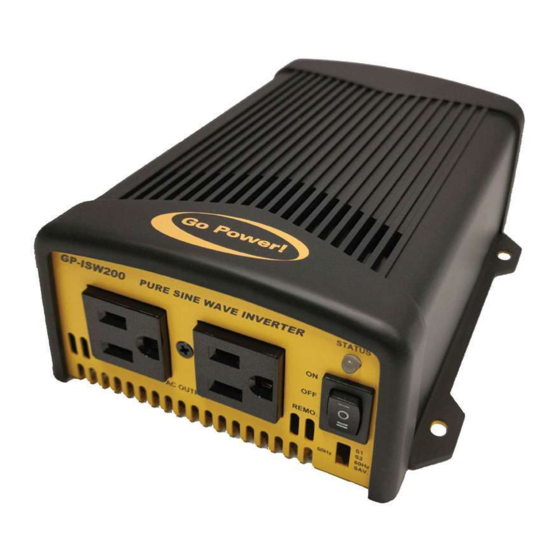
3. INSTALLATION Figure 1. GP-ISW-200 & 400 front panel view ON / OFF / Remote Main Switch LED Indicator AC Output Function Switch ON / OFF / Remote Main Switch The 3-stage switch is for turning on, turning off and remote mode. LED Indicator ... -
Page 16: Mounting Requirements
INSTALLATION 3.2 MOUNTING REQUIREMENTS 1. TEMPERATURE Make sure the GP-ISW is installed in a location where the normal air temperature is between -20°C and 40°C. The cooler the better within this range. 2. MOISTURE Do not allow water or other fluids to come into contact with the GP-ISW. Do not expose to rain, snow or water. - Page 17 INSTALLATION HORIZONTAL WALL MOUNT, BASE DOWN HORIZONTAL WALL MOUNT, BASE DOWN HORIZONTAL MOUNT, BASE DOWN HORIZONTAL MOUNT, BASE UP VERTICAL MOUNT, DO NOT MOUNT THE GP-ISW IN THIS CONFIGURATION *GP-ISW model may not be exactly as shown gpelectric.com | [page 17]...
-
Page 18: Dc Wiring
INSTALLATION 3.3 DC WIRING Solar Panel ISW Remote Control (Optional) GP-ISW Loads DC Panel Battery Disconnect Switch (not required if circuit breaker is used) Fuse or Circuit Breaker Earth Ground (RV Ground) Fuse Battery Bank To Battery Bank To Battery Bank The following points must be observed for the DC Wiring. -
Page 19: Dc Wiring Sizing
INSTALLATION 3.3.1 DC WIRING SIZING The distance between the battery bank and the GP-ISW should be as short as possible to achieve maximum efficiency and to reduce fire hazards. The size of the cable should be thick enough to limit the voltage drop to less than 2% when carrying the maximum input current to prevent frequent low- input voltage warnings and shutdown. -
Page 20: Dc Overcurrent Protection
INSTALLATION 3.3.2 DC OVERCURRENT PROTECTION AND DC DISCONNECT Batteries are capable of providing very large currents in case of a short circuit, if this occurs with no DC overcurrent protection, it will result in overheating and melting of the cables and possibly serious injury and/or fire. -
Page 21: Wiring The Inverter To The Batteries
INSTALLATION highly recommended. Apply the antioxidant grease or spray after all the connections are made and tightened. 3.3.5 WIRING THE INVERTER TO THE BATTERIES WARNING: Lethal currents will be present if the positive and negative cables attached to the battery bank touch each other. During the installation and wiring process, ensure the cable ends are insulated or covered to prevent shorting the cables. -
Page 22: Dc Grounding
INSTALLATION • Attach the red and black terminal covers over the Inverters DC connectors and secure them in place with the supplied screws. 3.3.6 DC GROUNDING To protect against electrical shock hazards the GP-ISW metal chassis must be connected to the DC grounding system. -
Page 23: Ac Output Interface
INSTALLATION 3.4.1 AC OUTPUT INTERFACE Socket Type (F) Model GP-ISW200/400-12/24 North America (GFCI) 3.4.2 GFCI (GROUND FAULT CIRCUIT INTERRUPTION) OUTLETS Compliance with UL standards requires that Go Power! test and recommend specific GFCIs for use on the AC output of the GP-ISW. GFCIs shall be installed in the AC output wiring system to protect all branch circuits. - Page 24 4. OPERATION 4. OPERATION GP-ISW-200 LED signal Status LED Signal Description Beep twice, LED shows red Power on orange green green R=red, O=orange, R=red Green LED lights in solid green Normal LED flashes green LED flashes green condition in intermittently once intermediate condition once Saving mode...
-
Page 25: Operation
LED flashes red light every 0.1 Shut down over seconds, then inverter shut voltage down. OPERATION LED flashes red light slowly Fan alarm once and quickly twice every 1.6 seconds GP-ISW-400 LED signal Table 7. GP200 & GP350 LED status ... -
Page 26: Testing The Installation
4. OPERATION 4.2 TESTING THE INSTALLATION 1. Apply battery power to the inverter by engaging the fuse or switching the breaker to the ON position. 2. Disconnect all AC loads from the inverter. 3. Press the ON/OFF button. The inverter will carry out self-diagnosis and the LED’s will also appear (various colors). -
Page 27: Inverter Status To Display Fault Condition
OPERATION Green 11.5 ~ 15.0V 23.0 ~ 30.0V Orange 15.0 ~ 15.5V 30.0 ~ 31.0V >15.5V >31.0V 4.4.2 INVERTER STATUS TO DISPLAY FAULT CONDITION LED status Status Recovery point Green Normal Over Current Protection / Over Load Protection (AC output short-circuit and over load) Under Voltage Protection 12.5V @ DC12V system 25V... -
Page 28: Function Switch
OPERATION 4.5 FUNCTION SWITCH 4.5.1 OUTPUT VOLTAGE SELECTION (S1&S2) Output Voltage 100V 110V 115V 120V 4.5.2 OUTPUT FREQUENCY SELECTION (S3) Frequency 50Hz 60Hz 4.6 POWER SAVING SELECTION (S4) Saving Function Power Saving OFF Power Saving ON [page 28] | gpelectric.com... -
Page 29: Shutdown Conditions
OPERATION 4.7 SHUTDOWN CONDITIONS Over Voltage (DC) Under Voltage (DC) Under GP-ISW200 Voltage /400 Alarm Shutdown Restart Shutdown Restart 10.5V ± 16V ± 0.3V 14.5V± 0.3V 10V ± 0.3V 12.5V± 0.3V 0.3V 33V ± 0.5V 29V ± 0.5V 21V± 0.5V 20V ±... -
Page 30: Warranty Return Procedure
5. WARRANTY RETURN PROCEDURE The Go Power! warranty is valid against defects in materials and workmanship for the specific product warranty period. It is not valid against defects resulting from, but not limited to: • Misuse and/or abuse, neglect or accident •... -
Page 31: Product End Of Life & Recycling
6. END OF LIFE - RECYCLING Product E.O.L (End of life) Information This product required the extraction and use of natural resources. It may con- tain substances that could be harmful to the environment or human health if improperly handled at the product’s end of life. In order to avoid release of such substances into the environment and to reduce the use of natural resources, we encourage you to recycle the GP-ISW in an appropriate way that will ensure most of the materials are reused or recycled appropriately. - Page 32 © 2021 Go Power! Worldwide Technical Support and Product Information gpelectric.com Go Power! | Dometic 201-710 Redbrick Street Victoria, BC, V8T 5J3 Tel: 1.866.247.6527 82654_MAN_ISW200-400_RevA...
Need help?
Do you have a question about the Go Power GP-ISW-200 and is the answer not in the manual?
Questions and answers