Table of Contents
Advertisement
Quick Links
Advertisement
Table of Contents

Related Manuals for Dometic Go Power! ECO SOLAR POWER KITS GP-ECO-10


Summary of Contents for Dometic Go Power! ECO SOLAR POWER KITS GP-ECO-10
- Page 1 ECO SOLAR POWER KITS User Manual GP-ECO-10 GP-ECO-20 GP-ECO-80 © 2022 Go Power! Worldwide Technical Support and Product Information gpelectric.com Go Power! | Dometic 201-710 Redbrick Street Victoria, BC, V8T 5J3 Tel: 1.866.247.6527 73839_MAN_GP_ECO_80_20_10_RevD...
-
Page 3: Table Of Contents
CONTENTS 2. GENERAL INFORMATION ..........................4 2.1 HOW DOES A GO POWER! SOLAR CHARGING KIT WORK? ............... 2.2 CAUTIONS ............................2.3 DISCLAIMERS ..........................2.4 KIT PARTS ............................2.4.1 PARTS CHECKLIST ....................... 2.5 REQUIRED TOOLS .......................... 3. PLANNING LOCATIONS ........................... 11 3.1 PLAN YOUR SOLAR SYSTEM SETUP .................... -
Page 4: General Information
2. GENERAL INFORMATION Congratulations on purchasing your Go Power! ECO Kit. You have chosen a clean, quiet and sustainable power source. Go Power! Solar Kits allow you to power appliances in your RV, without hooking up to shore power or a noisy generator. Go Power! Solar kits will keep your batteries charged, ensuring you have power when you need it. - Page 5 GENERAL INFORMATION Refrigerator Vent Cover or Cable Entry Plate Solar Panel MC4 Red Po MC4 Red Postive MC4 Black Negative Extension Cab Extension Cable (25 ft) Extension Cable (25 ft) PWM 10 Solar Charge Controller Fuse Legend Battery Bank MC4 Connector "CLICK"...
-
Page 6: Cautions
GENERAL INFORMATION 2.2 CAUTIONS disconnect all power Electricity can be very dangerous. Installation should be performed only sources before attempting by a licensed electrician or qualified personnel. installation Photovoltaic panels generate DC electricity when exposed to sunlight or other light sources. Contact with the electrically active parts of the panel, such as terminals, can result in burns, sparks and lethal shock whether the panel is connected or disconnected. -
Page 7: Disclaimers
GENERAL INFORMATION 2.3 DISCLAIMERS IMPORTANT: Please follow installation and wiring instructions exactly as outlined to ensure safety. We recommend installation by an RV technician or professional electrician to ensure adherence to relevant electrical codes. We have made every reasonable effort to ensure the accuracy of the instructions in this manual, but Go Power! does not guarantee that the information is error free, nor do we make any other representation, warranty or guarantee that the information is accurate, correct, reliable or current. -
Page 8: Kit Parts
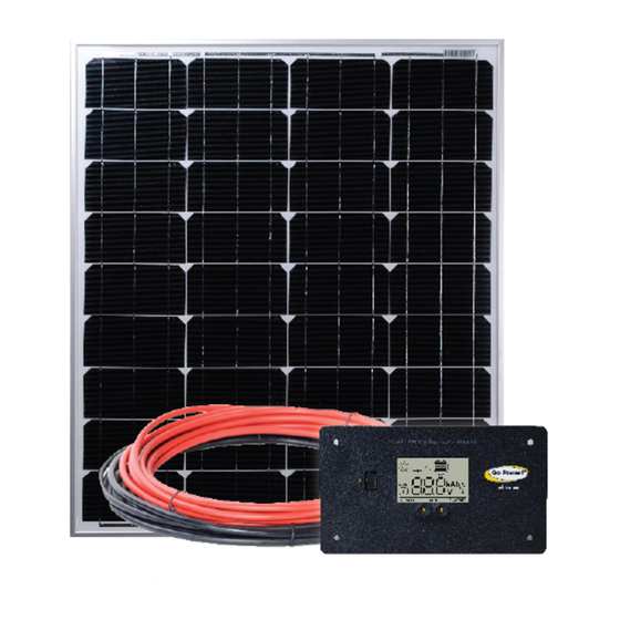
GENERAL INFORMATION 2.4 KIT PARTS Please unpack and make sure all parts shown in the list below are included in the kit. If any parts are missing please contact Note Go Power!’s customer service team at customerservice@gpelectric.com or 1.866.247.6527. 2.4.1 PARTS CHECKLIST ITEM # dESCRIPTION GP-PV-10, 10W Solar Panel (with fuse holder and fuse) - Page 9 GENERAL INFORMATION 8, 9 UNLESS OTHERWISE SPECIFIED PDM MAINTAINED DATA 250 Bay Street UNLESS OTHERWISE SPECIFIED PDM MAINTAINED DATA DO NOT SCALE DRAWING Victoria, BC Canada V9A 3K5 250 Bay Street CHANGES SHALL BE INCORPORATED Tel [250] 380-0052 DO NOT SCALE DRAWING ELECTRONICALLY BY THE DESIGN AUTHORITY Victoria, BC Canada V9A 3K5 INTERPRET DIMENSIONS AND TOLERANCES...
-
Page 10: Required Tools
GENERAL INFORMATION 2.5 REQUIRED TOOLS 1/16” and 3/8” Drill Bits Screwdriver (Phillips) Keyhole Saw 5/16” & 7/16” Wrench Pencil or Marker Heat Gun Pliers Caulking Gun Wire Strippers and Cutters Sealant Butt Splice Crimping Tool m. Digital Multimeter (troubleshooting only) Electric Hand Drill Torque Driver (optional) design your solar set up here:... -
Page 11: Planning Locations
3. PLANNING LOCATIONS 3.1 PLAN YOUR SOLAR SYSTEM SETUP 1. Take a few minutes before commencing any installation work to layout your solar system on paper first. Use the diagrams within this manual (pages 20-26) to help. 2. Complete a simple block diagram identifying the key components and connections of your solar charging system: Solar Panels, MC4 Positive and Negative Extension Cables (80W &... -
Page 12: Gp-Pwm-10 Solar Charge Controller
PLANNING LOCATIONS 3.3 LOCATING THE GP-PWM-10 AMP SOLAR CHARGE CONTROLLER The GP-PWM-10 solar charge controller is included in the Go Power! ECO 20W and 80W Kits. The GP-PWM-10 provides the necessary protection for the RV battery system. A condensed version of the installation instructions appear in this manual. However, please read the full installation manual included with the GP-PWM-10 solar charge controller. -
Page 13: Installation
4. INSTALLATION 4.1 MOUNTING FEET 1. Assemble 4 mounting feet onto each of the solar panels frame using the 1/4” bolts and nuts. This assembly is easily completed on the ground before the panels are brought up to the RV roof. (See Figure 4-A) WARNING: •... -
Page 14: Refrigerator Vent Access 1
INSTALLATIONS 4.3 REFRIGERATOR VENT ACCESS OPTION 1 Refrigerator Vent Cover Solar Module 1. Locate the refrigerator vent on the roof of the RV. Remove vent cover to gain access to the duct opening. Refrigerator 2. Drill a hole through the side of the vent (5/8” hole). Vent Cover 3. -
Page 15: Installing The Gp-Pwm-10 Solar Charge Controller (20W & 80W)
4. INSTALLATION 4.6 INSTALLING THE GP-PWM-10 SOLAR CHARGE CONTROLLER (20W & 80W) Ensure the Solar Panel is covered. Cover the panel faces completely with an opaque material to stop the production of electricity when working with panels or wiring – the cardboard shipping boxes are the perfect option to cover glass surface of the panels. 1. -
Page 16: Connecting To Battery Bank
INSTALLATIONS 4.8 CONNECTING THE BATTERY BANK It is recommended to connect directly to the battery whenever possible. You can also connect to the converter/charger where the battery positive and negative wires connect to the converter/charger 1. Clean all corrosion from the battery terminals before proceeding 2. -
Page 17: Maintenance
5. MAINTENANCE 5.1 INSPECTION After installing any Go Power Eco Kit or any other Go Power products it is prudent to complete a periodic check of all electrical and mechanical connections to ensure no connections have become loose or dislodged through transit vibrations. These checks should be carried out at least once after the initial kit installation and the first prolonged RV transit. -
Page 18: Specifications
6. SPECIFICATIONS GP-PV-10 Solar Panel Specs Rated power (Pm) Maximum power voltage (Vmp) 17.5V Maximum power current (Imp) 0.57A Open circuit voltage (Voc) 21.0V Short circuit current (Isc) 0.62A GP-PV-20 Solar Panel Specs Rated power (Pm) Maximum power voltage (Vmp) 17.5V Maximum power current (Imp) 1.14A... -
Page 19: Warranty Return Procedure
7. WARRANTY RETURN PROCEdURE The Go Power! warranty is valid against defects in materials and workmanship for the specific product warranty period. It is not valid against defects resulting from, but not limited to: • Misuse and/or abuse, neglect or accident •... -
Page 20: System Diagrams
8. SYSTEM dIAGRAMS GP-ECO-10 SYSTEM DIAGRAM Refrigerator Vent Cover or Cable Entry Plate ar Panel Solar Panel 5A Fuse (Included in Solar Panel Harness) Bank Battery Bank [page 20] | gpelectric.com... - Page 21 SYSTEM dIAGRAMS GP-ECO-20 SYSTEM DIAGRAM Refrigerator Vent Cover or Cable Entry Plate or Ca Solar Panel MC4 Red Postive MC4 Black Negative Extension Cable (25 ft) Extension Cable (25 ft) PWM 10 Solar Charge Controller Fuse Legend MC4 Connector Battery Bank "CLICK"...
- Page 22 © 2022 Go Power! Worldwide Technical Support and Product Information gpelectric.com Go Power! | Dometic 201-710 Redbrick Street Victoria, BC, V8T 5J3 Tel: 1.866.247.6527 73839_MAN_GP_ECO_80_20_10_RevD...
Need help?
Do you have a question about the Go Power! ECO SOLAR POWER KITS GP-ECO-10 and is the answer not in the manual?
Questions and answers