Advertisement
Quick Links
Dear Client
Thank you for Purchasing our HTFZ-III Arrester Discharge
Counter Calibrator. Please read the manual in detail prior to first
use, which will help you use the equipment skillfully.
company's products continually, so there may be
slight differences between your purchase equipment
and its instruction manual. You can find the changes
in the appendix. Sorry for the inconvenience. If you have further
questions, welcome to contact with our service department.
may bring voltage, when you plug/draw the test wire or
power outlet, they will cause electric spark. PLEASE
CAUTION RISK OF ELECTRICAL SHOCK!
Company Address:
T4,No. 41, High-tech 2 Road,East Lake High-tech Development Zone,
Wuhan
Sales Hotline: 86-27- 87457960
After Service Hotline: 86-27- 87459656
Fax: 86-27- 87803129
E-mail: qiao@hvtest.cc
Website: www.hvtest.cc
Our aim is to improve and perfect the
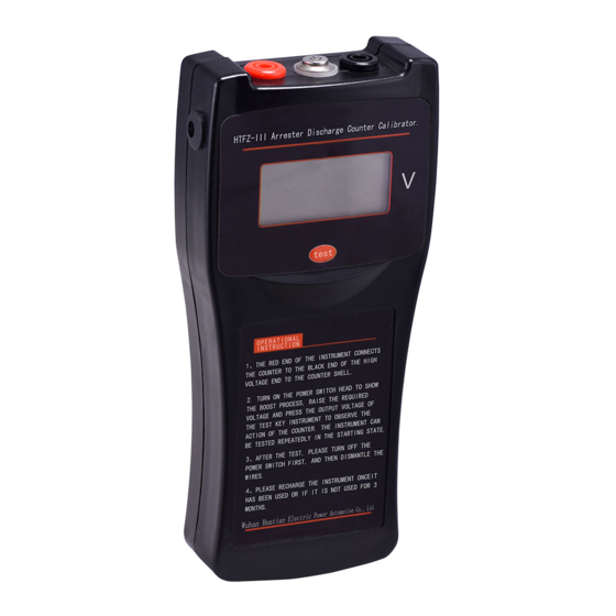
The input/output terminals and the test column
1
Advertisement

Subscribe to Our Youtube Channel
Related Manuals for HVTest HTFZ-III


Summary of Contents for HVTest HTFZ-III
- Page 1 Dear Client Thank you for Purchasing our HTFZ-III Arrester Discharge Counter Calibrator. Please read the manual in detail prior to first use, which will help you use the equipment skillfully. Our aim is to improve and perfect the company's products continually, so there may be slight differences between your purchase equipment and its instruction manual.
- Page 2 SERIOUS COMMITMENT All products of our company carry one year limited warranty from the date of shipment. If any such product proves defective during this warranty period we will maintain it for free. Meanwhile we implement lifetime service. Except otherwise agreed by contract.
- Page 3 shock, the grounding conductor must be connected to the ground. Make sure the product has been grounded correctly before connecting with the input/output port. Pay Attention to the Ratings of All Terminals To prevent the fire hazard or electric shock, please be care of all ratings and labels/marks of this product.
- Page 4 -Security Terms Warning: indicates that death or severe personal injury may result if proper precautions are not taken Caution: indicates that property damage may result if proper precautions are not taken.
-
Page 5: Table Of Contents
Contents I Principle..................7 II Technique Parameters............8 III Check method & principle..........8 IV Operation method............10 V Notes................... 12 VI Packing List...............12... - Page 6 Lightning arrester is an important electrical equipment to protect power equipment from over voltage in power grid.Normally, the arrester monitor is used to monitor the arrester's movement and leakage current. Due to poor sealing, the monitor may enter moisture or moisture during operation, which may cause corrosion of the internal components, or other causes that the monitor counter cannot operate normally, and the leakage current indication is inaccurate.So "<...
-
Page 7: I Principle
I Principle Fig 1 Circuit diagram for JS-type operating cycles counter (a) JS-type (b) JS-8 type R1, R2-nonlinear resistance C-Energy-storage capacitor L-Counter coil A silicon diode Figure 1 is circuit diagram of JS-type operating cycles counter. Figure 1 (a) shows circuit diagram of JS-type operating cycles counter, also called dual-valve plate structure. -
Page 8: Technique Parameters
is larger (1200A square wave), the minimum action current is 100A (8 / 20μs) impact current. JS-8 counter is suitable for 6.0 ~ 330kV arrester, JS-8A counter can be used for 500kV arrester. II Technique Parameters Parameters: The output voltage DC1600V ±5% Interval time ≥30s... - Page 9 Fig. 2 the principle circuit diagram for standard impulse current method (Impulse current generator in the dashed box) C---charging capacitor R---charging resistance L--- damped inductance D---Silicon rectifier diode r---Current divider B---Test transformer V---Electrostatic voltmeter CRO---high-voltage oscilloscope Let 8/20 μ s, 100A impulse current waves generated by impulse current generator act on operating cycles counter, if counter is functioning normally, which indicating the instrument is well, otherwise it should be repaired.
-
Page 10: Operation Method
IV Operation method... - Page 11 1. Let the output terminal of instrument connect to the two ends of arrester counter (the connecting lead should be as short as possible), red terminal connect to upper end, black terminal connect to earth terminal. 2. Well connect power cord (use DC power, need not connect power), then check whether the equipment and wiring are correct, confirm all is ok, you can start test.
-
Page 12: Notes
V Notes 1. Removing wiring, if the input voltage has not returned to zero, the operator can not touch the non-insulated part of test leads to avoid injury. 2. The tested target cannot bring voltage. 3. If DC power has run down, please charge up the battery in time. 4.
Need help?
Do you have a question about the HTFZ-III and is the answer not in the manual?
Questions and answers