Advertisement
Quick Links
Dear Client
Thank you for Purchasing our HTFZ-HI Arrester Discharge
Counter Calibrator. Please read the manual in detail prior to first
use, which will help you use the equipment skillfully.
company's products continually, so there may be
slight differences between your purchase equipment
and its instruction manual. You can find the changes
in the appendix. Sorry for the inconvenience. If you have further
questions, welcome to contact with our service department.
may bring voltage, when you plug/draw the test wire or
power outlet, they will cause electric spark. PLEASE
CAUTION RISK OF ELECTRICAL SHOCK!
Company Address:
T4,No. 41, High-tech 2 Road,East Lake High-tech Development Zone,
Wuhan
Sales Hotline: 86-27- 87457960
After Service Hotline: 86-27- 87459656
Fax: 86-27- 87803129
E-mail: qiao@hvtest.cc
Website: www.hvtest.cc
Our aim is to improve and perfect the
The input/output terminals and the test column
1
Advertisement

Subscribe to Our Youtube Channel
Related Manuals for HVTest HTFZ-HI


Summary of Contents for HVTest HTFZ-HI
- Page 1 Dear Client Thank you for Purchasing our HTFZ-HI Arrester Discharge Counter Calibrator. Please read the manual in detail prior to first use, which will help you use the equipment skillfully. Our aim is to improve and perfect the company's products continually, so there may be slight differences between your purchase equipment and its instruction manual.
- Page 2 SERIOUS COMMITMENT All products of our company carry one year limited warranty from the date of shipment. If any such product proves defective during this warranty period we will maintain it for free. Meanwhile we implement lifetime service. Except otherwise agreed by contract.
- Page 3 shock, the grounding conductor must be connected to the ground. Make sure the product has been grounded correctly before connecting with the input/output port. Pay Attention to the Ratings of All Terminals To prevent the fire hazard or electric shock, please be care of all ratings and labels/marks of this product.
- Page 4 -Security Terms Warning: indicates that death or severe personal injury may result if proper precautions are not taken Caution: indicates that property damage may result if proper precautions are not taken.
-
Page 5: Table Of Contents
Contents I Technique Parameters............6 II Panel diagram..............6 III Impulse test................. 7 IV Ammeter calibration..............9 V Notes..................10 V. Packing List................10... -
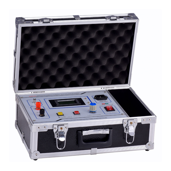
Page 6: I Technique Parameters
I Technique Parameters The function of the Arrester Discharge Counter Calibrator is not only to record the number of lightning strikes, but also to monitor the leakage current of the arrester online.Our newly developed lightning arrester online monitor calibrator is an instrument with both impact test and ammeter calibration functions. Parameters:... -
Page 7: Impulse Test
充电指示:Charging indicator III Impulse test 1. Test principle Fig 1 Circuit diagram for JS-type operating cycles counter (a) JS-type (b) JS-8 type R1, R2-nonlinear resistance C-Energy-storage capacitor L-Counter coil A silicon diode Figure 1 is circuit diagram of JS-type operating cycles counter. Figure 1 (a) shows circuit diagram of JS-type operating cycles counter, also called dual-valve plate structure. - Page 8 Figure 1 (b) shows circuit diagram of JS-8 type operating cycles counter, it is rectifier type structure. When the arrester operating, voltage drop on the valve R1 charge capacitor C through full-wave rectifier, then C discharge to L of electromagnetic counter and let it count. For this counter, the resistance value of valve R1 is small (when at 10kA, the voltage drop is 1.1kV), current capacity is larger (1200A square wave), the minimum action current is 100A (8 / 20μs) impact current.
-
Page 9: Ammeter Calibration
with damp and damaged. "Regulation" provides that continuously test for 3 to 5 times, each action should be normal, each time interval should be not less than 30s. After test logger should be set to zero. 3.Operation method 1. Let the output terminal of instrument connect to the two ends of arrester counter (the connecting lead should be as short as possible), red terminal connect to upper end, black terminal connect to earth terminal. -
Page 10: Notes
Under the shutdown state of the instrument, the wiring mode is the same as the impact test to form a circuit, after the wire is connected, press the current and voltage switch, and then can start! At this time, the instrument is in the state of electrical flow output.When checking, adjust the current to adjust the potentiometer, compare the instrument dial indication and the sample dial display, in order to determine whether the sample... - Page 11 1. Instrument host 2. Power cord 3. Test Wire 4. Grounding wire 5. The instruction manual 6. Certificate...
Need help?
Do you have a question about the HTFZ-HI and is the answer not in the manual?
Questions and answers