Advertisement
Quick Links
Dear Client
Thank
you
Capacitance Inductance Tester. Please read the manual in detail
prior to first use, which will help you use the equipment skillfully.
company's products continually, so there may be
slight differences between your purchase equipment
and its instruction manual. You can find the changes
in the appendix. Sorry for the inconvenience. If you have further
questions, welcome to contact with our service department.
may bring voltage, when you plug/draw the test wire or
power outlet, they will cause electric spark. PLEASE
CAUTION RISK OF ELECTRICAL SHOCK!
Company Address:
T4,No. 41, High-tech 2 Road,East Lake High-tech Development Zone,
Wuhan
Sales Hotline: 86-27- 87457960
After Service Hotline: 86-27- 87459656
Fax: 86-27- 87803129
E-mail: qiao@hvtest.cc
Website: www.hvtest.cc
for
Purchasing
Our aim is to improve and perfect the
The input/output terminals and the test column
our
HTRG-H
1
Automatic
Advertisement

Subscribe to Our Youtube Channel
Related Manuals for HVTest HTRG-H


Summary of Contents for HVTest HTRG-H
- Page 1 PLEASE CAUTION RISK OF ELECTRICAL SHOCK! Company Address: T4,No. 41, High-tech 2 Road,East Lake High-tech Development Zone, Wuhan Sales Hotline: 86-27- 87457960 After Service Hotline: 86-27- 87459656 Fax: 86-27- 87803129 E-mail: qiao@hvtest.cc Website: www.hvtest.cc...
- Page 2 SERIOUS COMMITMENT All products of our company carry one year limited warranty from the date of shipment. If any such product proves defective during this warranty period we will maintain it for free. Meanwhile we implement lifetime service. Except otherwise agreed by contract.
- Page 3 ground pole of the shell must be grounded. To prevent electric shock, the grounding conductor must be connected to the ground. Make sure the product has been grounded correctly before connecting with the input/output port. Pay Attention to the Ratings of All Terminals To prevent the fire hazard or electric shock, please be care of all ratings and labels/marks of this product.
- Page 4 -Security Terms Warning: indicates that death or severe personal injury may result if proper precautions are not taken Caution: indicates that property damage may result if proper precautions are not taken.
-
Page 5: Table Of Contents
Contents I. Product Overview.................. 6 II. Function Features.................6 III Technical Parameters................7 IV Working condition.................8 V Panel Introduction................. 8 VI Operation Introduction.................9 VII Attentions....................16 VIII Packing list..................17... -
Page 6: Product Overview
I. Product Overview In order to reduce reactive power loss in power system, shunt capacitor banks are usually used to improve power factor. In practical application, the accident rate of capacitor compensation device is relatively high, which is determined by the characteristics of the working state of capacitor device. Therefore, it is very important to check the capacitor device regularly and find capacitor defects early to avoid the expansion of the fault. -
Page 7: Technical Parameters
The instrument can display the current value and display the current frequency and other data; △-type and Y-type connection capacitors can also be measured besides the group of capacitors; 320×240 large-screen liquid crystal display and Chinese menu prompts makes it easy to operate;... -
Page 8: Working Condition
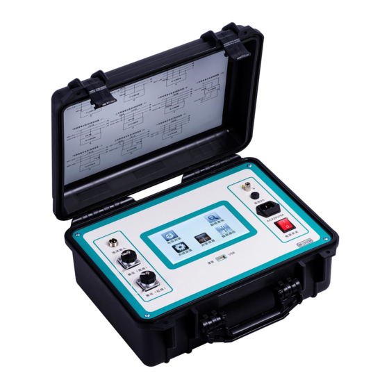
IV Working condition Ambient temperature -10℃~50℃ Ambient humidity ≤85%RH Working power supply AC220V±10% Power frequency 50±1Hz V Panel Introduction 1. Ux, Uo: voltage output test terminal 2. Current input: signal input socket for clamp current transformer ; 3. Power switch: power switch and insurance of the instrument; 4. -
Page 9: Operation Introduction
7. Printer: used to quickly print various data and curves; 8. RS-232: Used for data communication or software upgrade between the instrument and the PC. 9. USB interface: linked with large-capacity external mobile storage devices. VI Operation Introduction 6.1 Wiring Direction 6.1.1 Typical test wiring diagram of high voltage shunt capacitor: 6.1.2.Typical test wiring diagram of reactor:... - Page 10 6.2. Instrument Operation After the instrument is well connected to the power line in accordance with the requirement, turn on the power switch ,and the LCD will display the main menu which is shown in the following figure. 6.2.1 Capacitance Test In the interface of Main Menu , press the key <...
- Page 11 Among them: Test Power - refers to the test power supply provided for the test inside the instrument.Automatic voltage output or manual voltage regulation (4V, 20V, 120V) output can be selected. Connection—It means that the capacitor banks with Delta, Y and single-phase connections can be selected, when the capacitance is tested.
- Page 12 function options: Test, Stop, Save or Disp; press the key <↑>,<↓> to modify the phase of current capacitor under test (ab_bc_ca), while the single-phase capacitor is invalid. When modified to the required test items, press the function button Test to enter the capacitance test state, as shown in the left-top figure.
- Page 13 When the parameters are modified to meet the test requirements, select the function button OK and then press <OK> to return to the Test Options interface, select 3.Test Ind into the Testing Inductance interface: In the Testing Inductance interface, the current test results can be saved in local memory by pressing the key <...
- Page 14 In the Testing Current interface, the current test results can be saved in local memory by pressing the key < Save> , and the current test parameters and test results can be printed by pressing the key <print>. In the Testing Current interface, press the key < Back > to cut off the output of the test power, and return to the Test Options interface 6.2.4.
- Page 15 interface,The key <←> or <→> can be pressed to refer to different recorded data. Press the key < OK > to return to the History Record selection interface. In the History Record Data interface, press the key < Save > to save the current historical data to the USB disk, and press the <...
-
Page 16: Attentions
VII Attentions 7.1 Please read the instruction carefully before using this instrument. Check and ensure that the connection is correct and the ground is good. 7.2 High precision current clamp is the key component of the instrument,so it should be taken good care of during the process. 7.3 If the over voltage and over current protection act, identify the reasons and exclude the abnormal situation before continuing to test;... -
Page 17: Packing List
VIII Packing list Name Host Test leads(red/black with clip, 5M) 220V AC power cord Clamp Current Sensor USB communication wire Short circuit wire(with clip, 2m) Ground wire 5A fuse U-disk Instruction manual Test report Certificate...
Need help?
Do you have a question about the HTRG-H and is the answer not in the manual?
Questions and answers