Advertisement
Quick Links
Dear Client
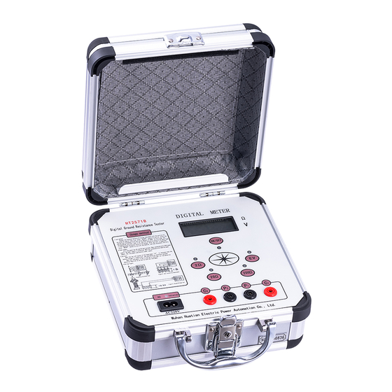
Thank you for Purchasing our HT2571B Earth Resistance
Tester. Please read the manual in detail prior to first use, which will
help you use the equipment skillfully.
company's products continually, so there may be
slight differences between your purchase equipment
and its instruction manual. You can find the changes
in the appendix. Sorry for the inconvenience. If you have further
questions, welcome to contact with our service department.
may bring voltage, when you plug/draw the test wire or
power outlet, they will cause electric spark. PLEASE
CAUTION RISK OF ELECTRICAL SHOCK!
Company Address:
T4,No. 41, High-tech 2 Road,East Lake High-tech Development Zone,
Wuhan
Sales Hotline: 86-27- 87457960
After Service Hotline: 86-27- 87459656
Fax: 86-27- 87803129
E-mail: qiao@hvtest.cc
Website: www.hvtest.cc
Our aim is to improve and perfect the
The input/output terminals and the test column
1
Advertisement

Related Manuals for HVTest HT2571B


Summary of Contents for HVTest HT2571B
- Page 1 Dear Client Thank you for Purchasing our HT2571B Earth Resistance Tester. Please read the manual in detail prior to first use, which will help you use the equipment skillfully. Our aim is to improve and perfect the company's products continually, so there may be slight differences between your purchase equipment and its instruction manual.
- Page 2 SERIOUS COMMITMENT All products of our company carry one year limited warranty from the date of shipment. If any such product proves defective during this warranty period we will maintain it for free. Meanwhile we implement lifetime service. Except otherwise agreed by contract.
- Page 3 ground pole of the shell must be grounded. To prevent electric shock, the grounding conductor must be connected to the ground. Make sure the product has been grounded correctly before connecting with the input/output port. Pay Attention to the Ratings of All Terminals To prevent the fire hazard or electric shock, please be care of all ratings and labels/marks of this product.
- Page 4 -Security Terms Warning: indicates that death or severe personal injury may result if proper precautions are not taken Caution: indicates that property damage may result if proper precautions are not taken.
-
Page 5: Table Of Contents
Contents I. Introduction··························································· 6 II. Technical Specifications·········································· 8 III. Operation Instructions·············································9 IV. Notes··································································· 11 V. Packing list···························································13... -
Page 6: Introduction
I. Introduction 1. Working Principle The instrument is a newly developed earth resistance tester, which abandons the traditional way of generating electricity by hand operation, uses advanced middle-large scale integrated circuits and applies DC/AC transformation technology to combine three-terminal measurement method and four-terminal measurement method into one model. - Page 7 this instrument can also measure soil resistivity and ground voltage. 3. Main features High-strength aluminum alloy shell body, the circuit equipped with phase locked loop and switched capacitor filter, based on which the instrument play an effective role in shielding power frequency and radio frequency interference.
-
Page 8: Technical Specifications
II. Technical Specifications 1. Operating Conditions Temperature: 0 ℃ ~ +45 ℃ Relative humidity: ≤ 85% 2. Measuring range and constant current value (virtual value) Resistance: 0 ~ 20Ω (10mA), 2 ~ 200Ω (1mA), 20 ~ 2000Ω (0.1mA) Voltage: AC 0 ~ 19.99V 3. -
Page 9: Operation Instructions
Maximum power dissipation≤ 2W DC: 8 × 1.5V (AA, R6) Battery AC: 220V/50Hz 6. Dimensions and weight Dimensions: 220× 200 × 105mm Weight: ≤ 1.4kg III. Operation Instructions 1. Grounding resistance measurement (Fig. 1) As Fig.1, the straight-line distance between ground electrode E (C2, P2) and current probe C1is 40 meters. - Page 10 their corresponding probes with special wire. Turn on the power switch; select the appropriate gear and press the “confirm” key, at selected gear the indicator lights, data display on LCD is the measured ground resistance. 2. Soil resistivity measurement (Fig. 2) As Fig.
-
Page 11: Notes
where probes were inserted. The probe used for measuring grounding resistance and soil resistivity is aluminum tube or round steel. Generally its diameter is 25mm and its length is 0.5 ~ 1m. 3. Conductor resistance measurement (Fig. 3) 4. Ground voltage measurement Wiring as Fig. - Page 12 2. When measuring and protecting grounding resistance, you must disconnect power supply. For grounding resistance is less than 1Ω, you should separately connect it to the grounding object with special lead, C2 on the outside, P2 in the medial. Shown in Fig. 4: 3.
-
Page 13: Packing List
6. “←” appearing on the top left corner of the screen says battery voltage is low and you should replace a new battery. If the instrument will not be used for a long time, all batteries should be removed to prevent the instrument from corrosion.
Need help?
Do you have a question about the HT2571B and is the answer not in the manual?
Questions and answers