Table of Contents
Advertisement
Quick Links
Dear Client
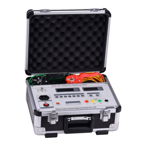
Thank you for Purchasing our HTZZ-2A Transformer DC
Winding Resistance Tester. Please read the manual in detail prior
to first use, which will help you use the equipment skillfully.
company's products continually, so there may be
slight differences between your purchase equipment
and its instruction manual. You can find the changes
in the appendix. Sorry for the inconvenience. If you have further
questions, welcome to contact with our service department.
may bring voltage, when you plug/draw the test wire or
power outlet, they will cause electric spark. PLEASE
CAUTION RISK OF ELECTRICAL SHOCK!
Company Address:
T4,No. 41, High-tech 2 Road,East Lake High-tech Development Zone,
Wuhan
Sales Hotline: 86-27- 87457960
After Service Hotline: 86-27- 87459656
Fax: 86-27- 87803129
E-mail: qiao@hvtest.cc
Website: www.hvtest.cc
Our aim is to improve and perfect the
The input/output terminals and the test column
1
Advertisement
Table of Contents

Subscribe to Our Youtube Channel
Related Manuals for HVTest HTZZ-2A


Summary of Contents for HVTest HTZZ-2A
- Page 1 Dear Client Thank you for Purchasing our HTZZ-2A Transformer DC Winding Resistance Tester. Please read the manual in detail prior to first use, which will help you use the equipment skillfully. Our aim is to improve and perfect the company's products continually, so there may be slight differences between your purchase equipment and its instruction manual.
- Page 2 SERIOUS COMMITMENT All products of our company carry one year limited warranty from the date of shipment. If any such product proves defective during this warranty period we will maintain it for free. Meanwhile we implement lifetime service. Except otherwise agreed by contract.
- Page 3 shock, the grounding conductor must be connected to the ground. Make sure the product has been grounded correctly before connecting with the input/output port. Pay Attention to the Ratings of All Terminals To prevent the fire hazard or electric shock, please be care of all ratings and labels/marks of this product.
- Page 4 -Security Terms Warning: indicates that death or severe personal injury may result if proper precautions are not taken Caution: indicates that property damage may result if proper precautions are not taken.
-
Page 5: Table Of Contents
Contents I. Overview....................6 II. Application..................... 7 III. Performance characteristics .............. 7 IV. Specifications..................8 V. Panel Layout..................10 VI. Working Principle ................10 VII. Operation Methods................11 VIII. Problems and Solutions..............14 IX. Notes ....................14... -
Page 6: Overview
I. Overview DC resistance measurement of transformer winding is an essential test project during transformer transfer, repair and changing tapping switch. Measuring DC resistance of transformer winding, you can check out weld or connection quality of down-lead, the winding inter-turn short circuit or open circuit, and whether tap-changer is well contacted. -
Page 7: Application
power consumption, stable and reliable test data. Built-in rechargeable battery pack (14.8V) and AC/DC dual-use, the instrument is very convenient for on-site and field test. instrument meets 845.3-2004 "resistance measurement device general technical requirements- Part 3 DC Resistance Tester" requirements. II. -
Page 8: Specifications
relatively stable value. Base on that, and the instrument with stable anti-sense capability and strong anti-interference characteristics can ensure the accuracy of measurement. And the use of imported high-quality components not only improves the measurement accuracy, but also makes the instrument have good repeatability. 3. - Page 9 2kΩ~20kΩ 3. Measurement Accuracy:±(0.2%+2d) 4. Maximum Resolution: 1μΩ 5. Constant current source: 2A (1μΩ~20mΩ, 20 mΩ~200mΩ, 0.2Ω~2Ω); 200mA (2Ω~20Ω); 10mA (20Ω~200Ω); 1mA (200Ω~2kΩ) 100uA(2kΩ~20kΩ) 6. Working Voltage: DC: 12V~16.8V AC: 220V 7. Power Dissipation: ≤15W 8. Dimension: 365×330×180mm 9. Weight:5kg (included test clamp and test lead)
-
Page 10: Panel Layout
V. Panel Layout Picture 1 panel layout 1. resistance range select 2. resistance 3. Tem/current 4 .Tem sensor 5.Tem/current select 6. test line jack 7 .working status 8 .start/stop 9 .power switch 10 .power indicator 11. 220V plug 12. ground VI. -
Page 11: Operation Methods
the instrument at terminals V +, V, after amplification, the display will show the resistance value using four and a half bits LCD digital. VII. Operation Methods 1. Power supply This instrument provides two power sources for test: AC220V/DC14.8V. case strong electromagnetic interference, the best choice is use the DC power supply for test. - Page 12 press “start/stop” button, "discharge" indicator lights (if the stored electricity of tested object is little, the "discharge" indicator does not light), after discharge, "discharge" indicator goes out, and then convert the test clip for re-test. 3) Charge Connect to AC220V power supply, "charging" indicator lights indicating the rechargeable battery is charging.
- Page 13 In measuring, if the length of test line is not enough, you can use lead having same size diameter to extend it. 3. Measurement Well connected the test line as fig. 2, closed power switch, power indicator lights, and press the "start/stop" button, then the display shows "E0000".
-
Page 14: Problems And Solutions
VIII. Problems and Solutions Problems Solutions Did not choose resistance range. Display resistance Wiring error. value “E0000” Tested resistance value exceeds rang, please connect to large range. The screen do not display resistance Did not press “Start/Stop” key. value IX. Notes 1.
Need help?
Do you have a question about the HTZZ-2A and is the answer not in the manual?
Questions and answers