Table of Contents
Advertisement
Quick Links
Dear Client
Thank you for Purchasing our HT-802 Protection Relay Test Set. Please
read the manual in detail prior to first use, which will help you use the equipment
skillfully.
continually, so there may be slight differences between your
purchase equipment and its instruction manual. You can find the
changes in the appendix. Sorry for the inconvenience. If you
have further questions, welcome to contact with our service department.
The input/output terminals and the test column may bring
voltage, when you plug/draw the test wire or power outlet, they will
cause electric spark. PLEASE CAUTION RISK OF ELECTRICAL
SHOCK!
Company Address:
T4,No. 41, High-tech 2 Road,East Lake High-tech Development Zone, Wuhan
Sales Hotline: 86-27- 87457960
After Service Hotline: 86-27- 87459656
Fax: 86-27- 87803129
E-mail: qiao@hvtest.cc
Website: www.hvtest.cc
Our aim is to improve and perfect the company's products
1
Advertisement
Table of Contents

Subscribe to Our Youtube Channel
Related Manuals for HVTest HT-802


Summary of Contents for HVTest HT-802
- Page 1 Dear Client Thank you for Purchasing our HT-802 Protection Relay Test Set. Please read the manual in detail prior to first use, which will help you use the equipment skillfully. Our aim is to improve and perfect the company's products continually, so there may be slight differences between your purchase equipment and its instruction manual.
- Page 2 SERIOUS COMMITMENT All products of our company carry one year limited warranty from the date of shipment. If any such product proves defective during this warranty period we will maintain it for free. Meanwhile we implement lifetime service. Except otherwise agreed by contract.
- Page 3 The product is grounded through the power wire; besides, the ground pole of the shell must be grounded. To prevent electric shock, the grounding conductor must be connected to the ground. Make sure the product has been grounded correctly before connecting with the input/output port.
- Page 4 -Security Terms Warning: indicates that death or severe personal injury may result if proper precautions are not taken Caution: indicates that property damage may result if proper precautions are not taken.
-
Page 5: Table Of Contents
Contents ........6 HAPTER NSTRUMENT CHARACTERISTICS AND TECHNIQUE PARAMETERS Section 1 Main characteristics..................... 6 Section 2 Technique parameters....................7 ....................9 HAPTER ARDWARE STRUCTURE Section 1 hardware components....................9 Section 2 Instruction of panel.....................11 ......................13 HAPTER SE THE TESTER Section 1 General Rules for Use....................13 Section 2 Procedures of starting up/shutdown................14 Section 3 relay protection test item................... -
Page 6: Chapter 1 Instrument Characteristics And Technique Parameters
Chapter 1 Instrument characteristics and technique parameters Section 1 Main characteristics 1. Meets all the requirement of field tests. This tester with standard 4 phase voltage, 3 phase current output, voltage 125V/phase, current 40A/phase, 3 phases in parallel can up to 120A. -
Page 7: Section 2 Technique Parameters
10. With GPS synchronization test function. The device can be built-in GPS synchronization card (optional) connects with PC by RS232; people can do remote synchronization swap test for the two testers. 11. With a separate DC auxiliary voltage source, output voltage 110V(1A),220V(0.6A), provides relays or protective devices which require DC power. - Page 8 Phase voltage output range: 0~±150V accuracy: 0.5% Line voltage output range: 0~±300V Phase voltage / Line voltage output power: 970VA / 180VA 5. Switch terminal Switch input terminals: 8 pairs Dead contact: 1-20mA, 24V active output inside the device. Potential flip: 0--6V DC low level 15-250V DC high level Switch output terminals: 4 pairs, dead contact, rupturing capacity: 110V/2A, 220V/1A 6.
-
Page 9: Chapter 2 Hardware Structure
Chapter 2 Hardware structure Section 1 hardware components 1. Built-in high-performance industrial control computer This device uses high - performance IPC control computer, with self- restore the CF card, 8.4 " 800 × 600 resolution TFT color LCD. This machine with special high-performance industrial keyboard and mouse can directly use no need connect other instruments, software running under Windows XP operating system, easy to operate. - Page 10 overvoltage and short circuit protection functions. Current loop allows open circuit, will not damage the device. There is current open circuit indicator on the panel for users to check if wiring corrected. The panel also with over-voltage or short circuit indicators, when there was short circuit on voltage circuit (if with output), the indicator will be on and start the buzzer alarm.
-
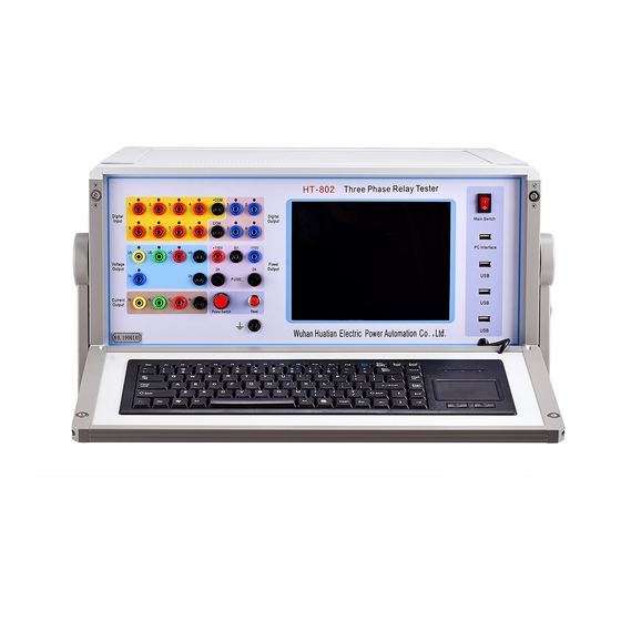
Page 11: Section 2 Instruction Of Panel
(3) Dead contact 6. Independent DC power output This device with 2 circuits 110V DC power output, end to end compose to +110V、0V、 -110V three terminals output, only can be the power of the protection device, not be the DC operating power. - Page 12 5. Fixed output: +110V, 0V, -110V; 6. Amplifier switch: open this when the device need output current, voltage; 7. Reset 8. Grounding terminal: well grounded during test; 9. Fuse : fixed output +110V, -110V; 10. LCD: 8.4”;11.0 Host switch: power of the IPC; 12.
-
Page 13: Chapter 3 Use The Tester
Chapter 3 Use the tester Section 1 General Rules for Use 1. This tester with IPC and Windows operating system, please do not power on/off frequently. 2. There are USB interfaces on the panel or backboard, which allow hot-swap USB equipment (such as flash disk, etc), but this must be done after the data transmission completed. -
Page 14: Section 2 Procedures Of Starting Up/Shutdown
10. If there were data error, can not connect the device or other problems during use , it can be solved: exit back to the main menu and re-run the program , then all the data are restored to default values. Section 2 Procedures of starting up/shutdown 1. -
Page 15: Section 3 Relay Protection Test Item
Section 3 relay protection test item 1. Relay test Relay type Test item Test module Note If the relay with AC/DC input, please Signal relay choose “AC/DC test”. AC test Time relay For the signal relay with small rated Relative test item Intermediate relay current, please choose voltage loop test Intermediate relay... - Page 16 2. Microprocessor-based protection device Types of relay protection Test item Test module Note Multi-stage over-current Can do most of the relay and micro computer test at “AC test” Over (less ) voltage AC Test module. Sequence components Frequency Test voltage and current Relative test item Power direction Frequency devices...
- Page 17 Harmonic test curve characteristics search, includes Proportion of braking border search , proportion of braking designated test, harmonic brake border search harmonic restraint sentinel test , comprehensive test differential protection . Please note angle Field loss protection Relative test item AC test between output current and Excitation protection...
-
Page 18: Chapter 4 Introduction Of Software Operation
Chapter 4 Introduction of Software Operation Section 1 Software and driver installation 1. Software installation Each tester is equipped with a software U-disk which includes 3 files: SETUP.EXE, driver, instruction manual. IPC and PC are installed application software and USB driver before delivery, double click SETUP.EXE to re-install, follow the prompts, the program will automatically complete the installation. -
Page 19: Section 2 Ac Test
4. Report management Can choose from a variety of test report to preview, print arrange, delete, and copy. Section 2 AC Test 1. Interface Instruction... - Page 20 [AC test] module is a general, integrated test modules, it consists of a separate 3 -phase current and 4 phase voltage (this instrument). By setting the corresponding voltage or current as a variable, assigned a certain change to the variable step length, and selects the appropriate test methods ( e.g.
- Page 21 relay action can record the action value and action time, then terminate the tester output, the program automatically returns. (7) [Manual test ( the action returns ) ] The program continuous output current value, click【 ▲ 】 button the variable amount that increments a step, click [ ▼...
- Page 22 (1) [action input value] Input value is 1 - 8 optional, which access to the normally open contact or normally closed contact of the relay. (2) [action output value] When the contacts of the relay operate, and give one output value, usually open- close, maintaining time is 1 second, which used to start the waveform recorder or milliseconds.
- Page 23 2. Test functions introduction (1) Voltage, current tests Select a phase voltage or a phase current as variable, select automatic or manual test changes until the relay actions. When the voltage is more than 125V, current is more than 30A, the voltage can be line voltage output, such as UAB, UBC, and UCA. The current can output by two phases or three-phase in parallel, note the current phase should be the same phase.
- Page 24 contact access the tester switch input terminal 1 , set IA = 6A, IB = IC = 0 , UA = UB = UC = 57V , the phase difference is 120 degree . Select UA, UB and UC variable, 60/1.732 = 34.64, [Manual test] way diminishing the three-phase voltage, UA = UB = UC = 34.64V protection action.
-
Page 25: Section 3 Dc Test
③ Wiring - as shown : Section 3 DC Test This test module provides specialized DC voltage and DC current output, mainly to meet the test requirements for DC voltage relay, time relay, and intermediate relay. The main interface as shown in the figure, its operation methods are basically the same with [AC test]. - Page 26 1. Test functions introduction (1) time relay ① Action time test Applied rated DC voltage (typically 220V) to the coil of the, the action contacts of delay access tester open intake, set UA = 110V, UB = -110V, UAB line voltage access relay voltage coil, use [manual test ( stop action ) ] output can measure action time of the time relay .
-
Page 27: Section 4 Frequency Test
Signal relay wiring Time relay wiring Section 4 Frequency Test The module is mainly used testing low cycle load shedding and circumferential resection protection features. 1. [Action frequency ( return frequency ) test] If start frequency was greater than the stop frequency, low-frequency test is needed; Start frequency was less than the stop frequency, high-frequency test is needed, the program automatically discriminating the direction of change of the frequency. - Page 28 2. [Action time (Slip lock) test ] Different with operating frequency (return frequency) it changes frequency accord rate, only a heuristic approach to test. For example : a protection known slip lock value is 3.00Hz / s, we first set [ slip value ] 3.10Hz / s to test , if the protection does not act, we again set [ slip value ] to be 2.90Hz / s to test, if the protection acts, then 3.00Hz / S slip lock value is correct.
-
Page 29: Section 5 Synchronous Test
Section 5 Synchronous Test This module is used to test the operation voltage, operating frequency, the action angle of the synchronization device as well as automatically adjusting test quasi-synchronization test. 1. Interface Instruction (1) Use this procedure; the tester only output voltage, no output current. General system side elect UA, the shunt side elect UB, input terminal choose from 1-8. - Page 30 System side voltage UA = 100V, phase 0 degree, frequency 50Hz. System side parameter is constant value. Set the shunt side voltage UB = 90V, 0 ° phase, frequency 50Hz. It can be seen that only amplitude is not a constant, the other two meet the conditions , manually or automatically increments UB, when it closes to UA phase amplitude , synchronization device acts, the program records the UB amplitude to be the action voltage value.
- Page 31 synchronization device. It connects to input value to change the frequency and the amplitude. Program defined input terminal 5 is increasing frequency, input terminal 6 is less frequency, input terminal 7 is pressurized, 8 is decompression. Action contacts Optional from 1-4 input terminals, if the synchronizing conditions are met, the tester records the operation frequency and operation voltage.
-
Page 32: Section 6 Current&Voltage Test
Section 6 Current & Voltage Test This test module is designed for testing current relays and voltage relays. Given the value of the start and end of the current, voltage value and changeable step parameters, the program will automatically test the relay action and return values, and automatically calculates the return coefficient. -
Page 33: Section 7 Differential Test
The output voltage of the tester connects to the voltage coil of the relay, the input terminal 1 is connected to the relay action contacts, when the starting voltage is less than the termination voltage, the program will automatically test the voltage in increment; When starting voltage is greater than the termination voltage, the program automatically test the voltage in descending and automatic measure the return voltage and calculate return voltage coefficient. - Page 34 adjusted. For details, please see the connecting mode. The phase difference of IA and IB is 0 degrees or 180 degrees. When ‘Six Phases Differential’ is selected, IA, IB, IC and IN should be connected with current input ends A, B, C and N on the high voltage side and connecting Ia, Ib, Ic and In with current input ends a, b, c and N on the low voltage side.
- Page 35 principle, the current output adopts intermittent output. Calculating formula Choose calculating formula that manufacturer provided, in which I1 (IA) for the high side current, I2 (IB) for the low (middle) side current, K1 for the balance coefficient of the high side, K2 for the balance coefficient of low (middle) side.
- Page 36 If setting equilibrium factor on high voltage side to be 1, and convert other sides to high voltage side, its calculation formula is as follows: K1=1 K2=U2n*CT2/(*U1n*CT1) K3=1.732*U3n*CT3/(U1n*CT1) c) Calculating equilibrium factor in terms of rated current is as following: K1=1 K2=Ie1/Ie2 K3=Ie1/Ie3...
- Page 37 Let the first group of three-phase current connect to high voltage side; let the second group of three-phase current connect to low voltage side. The connecting mode is very simple. Connecting mode of three-phase ratio control There are six different connecting modes, including current compensation. ○...
- Page 38 ○ 3 、Y(Y0)/ △-1 Connecting mode Connecting mode of harmonic restraint Connecting mode of six-phase current Connecting mode of three-phase current (6) Test item When all the parameters are well set, we can conduct various test Ratio Control Boundary Search...
- Page 39 Select ‘Add Sequence’ button, then pop-up dialog to select a set of brake current: ‘original value’ and ‘final value’; step size is generally 2.00A. After completing the set of parameters, click ‘Add’ for putting the data in the testing data list, then select ‘start’. Ratio Restraint Setting Point Search Move the mouse to the coordinate system of the characteristic curve, click the left mouse button, then select ‘Add setting point’...
- Page 40 Harmonic Restraint Setting Point Search Move the mouse to the coordinate system of the characteristic curve, click the left mouse button, then select ‘Add setting point’ button for putting this point in the testing data list, repeat the above operation to add multiple test points, as shown in the figure. The test points should be selected in the action area and non-operating area, in order to verify whether the curve is correct.
-
Page 41: Section 8 Impedance Characteristic
current equals to the difference of the current from two sides, both sides of the current phase difference is 0 degree. (4) When doing the test by three-phase current, if compensating current does not be included, test results will also be incorrect. Since the three-phase current can only do split-phase differential test, and the connecting mode of the transformer is different, both sides of the current will produce a certain phase difference, thereby the protective device must be done phase compensation in the software. - Page 42 In the coordinate system moving the mouse, click the left button, can change the scanning center, users estimate the position of the scanning center based on the impedance characteristics. 2. [Scanning radius] Full 360 -degree scan, scanning radius determine the scanning range, the scanning radius should be larger than the impedance tuning value.
-
Page 43: Section 9 Harmonic Test
Section 9 Harmonic Test The program outputs three-phase current and three-phase voltage, each phase current and voltage can superimpose 2 harmonic on the first harmonic, the amplitude and phase of each harmonic can be arbitrarily changed, and can be used to test various devices of reflecting the harmonic components. -
Page 44: Section 10 Power Direction Test
Section 10 Power Direction Test This module is special for power direction relay test, which divided into two trials according to the power direction relay wiring, the first 0 degrees wiring, second is 90 degrees wiring. User-selectable any way wiring, the program automatically dichotomy test boundary corner, and automatically calculates the power direction relay sensitive angle. -
Page 45: Section 11 Impedance Test
Section 11 Impedance Test This program is used for the impedance setting calibration of the three-stage or four-stage distance protection. Generally the substations which more than of 110KV voltage levels equip with distance protection device. 1. [ Inter-phase setting ] Inter-phase impedance short - circuit setting, the program set to four stages, i.e., Z1, Z2, Z3 and Z4. - Page 46 impedance angle (sensitivity angle ) is generally 90 degrees or 80 degrees . Two ways optional, the program automatically translated. Generally protection only has three sections, enter the setting values to a fixed value of the column during the test. If without the fourth setting , do set it , at the same time in the [ Test Project ] column do not select Ⅳ.
- Page 47 short-circuit current is generally set to be lower, which can be selected according to the specific circumstances. 5. [Test item] This test project contains 0.7 times, 0.95 times, 1.05 times, 1.1 times of four kinds of multiples of 1-4 section impedance given value, and generally takes the value of 0.7 times, 0.95 times, 1.05 times to test.
-
Page 48: Section 12 Zero Sequence Protection
Section 12 Zero Sequence Protection This program is designed to test zero-sequence over-current project of distance protection and zero sequence over-current generally divided into four sections, section 1 is generally quick break, Section 2, 3 and 4 general are exports with a delay, action time and current in inversely proportional. - Page 49 Respectively enter the current setting of section 1, 2, 3 and 4 according to the protection setting. Normal state time should be more than the protection entire group of reversion time, typically 20 seconds; fault state time should be more than zero sequence four sections time, usually 4 seconds.
-
Page 50: Section 13 Group Test
4. [Switching value] Contact 1 select the triple jump, and others closing 5. Protection on/off Only zero sequence on, others off. 6. Wring-as shown Section 13 Group Test... - Page 51 The program can simulate transient, permanent and transitional fault for the reclosing test of the circuit protection, after accelerated and whole drive test with switch. 1. [Parameters setting] [Fault nature]: transient faults, permanent faults and conversion failure optional. [PT installation]: bus side or line side. If bus side, when the switch is tripped, the voltage loop revert to the normal state voltage, current 0A.
- Page 52 [Fault type]: AN,BN,CN;AB,BC,CA;ABN,BCN,CAN and ABC。 [Short circuit current]: the current value of the fault phase should be greater than the protection operating current, and generally 5A. (Fault model is valid when the current is constant). [Short circuit voltage]: the voltage value of the fault phase should be less than normal voltage of 57V, and generally 25V.
- Page 53 terminal 1 close. The failure 2 trip switching output terminal 2 is closed. Switching output terminal 3 is closed when the reclose of the protection operates. Protection Wing trip (second trip), switching output terminal 4 closed. 5. [Calculation model ] (1) The current is constant: to calculate the short - circuit voltage according the short circuit current, observe it by the current, voltage amplitude of each states and vectors.
-
Page 54: Section 14 State Sequence Test
8. Wiring-as shown Section 14 State Sequence Test This procedure continuous output for plurality states at a given time, starting from the initial state until the end state, 20 states the most. State types can be divided into : no-load , any ;... - Page 55 Program default 2 states, the initial state and end state. The middle can be inserted various fault states, the best insert a no-load state as a transitional state between two fault state , the time of the state to be elected more than 10 seconds , so that the protection of the entire group of reversion or reclosing charging is completed .
-
Page 56: Section 15 Inverse Time Overcurrent Relay Test
Section 15 Inverse Time Overcurrent Relay Test Set a group of current, the program automatically test the operating time of each current relay, and draw the relation curve between operating current and the action time. Single phase inverse time tests and three phase inverse time tests are available. 1. -
Page 57: Section 16 Differential Relay Test
Generally are single-phase current, when the current is relatively large, can choose parallel two-phase or three-phase in parallel output. The program automatic set the current phase to be same phase, meanwhile automatically assigned the current average to each phase current output, the users need not recalculate. The three phase inverse time test, three-phase current output debug current, and phase difference between each 120 degrees. - Page 58 1. Interface introduction (1) [Test project selection] [Proportional braking], [DC Assistant magnetic] 2 alternative projects. (2) [ Test current ] select IA is operating current (ID). IB is breaking current or assistant magnetic DC (IZ). (3) [ Starting current ] The minimum operating current in the case of no braking.
-
Page 59: Section 17 Intermediate Relay
group data of braking in the test results column, users can directly modify. 2. Test Principle The program automatic test the operating current corresponding to each braking current, and draw action curve in the coordinate system. Users select two points in the braking current to calculate the braking coefficient. - Page 60 3. Parameter selection (1) [The starting voltage] is generally 50.00V; [termination voltage] is generally 220.00V. (2) [The starting current] usually is 1.00A; [termination current] is generally 10.00A.(3) [Maintain voltage] usually is 110V or 220V. (4) [Maintain current] is usually 2.00A. (5) [Voltage step] is usually 0.5V or 1.00V.
-
Page 61: Section 18 Frequency Variation Test
Section 18 Frequency Variation Test The program respectively simulates U-phase, V-phase, W-phase single-phase ground transient fault and uv, vw, wu phase to phase transient failure. Simulated fault current is a fixed current; simulated pre-fault voltage is rated voltage 57.73V; simulated failure time is generally 100-150ms. -
Page 62: Section 19 Failure Recurrence
Tester Protector Input Output Section 19 Failure Recurrence This program can read out the Comrades format recorded wave file, and display substation name, the number of analog channels, the number of switching value channels, the sampling frequency of the data in each segment, the sampling points and the total sampling points in the interface. -
Page 63: Section 20 System Vibration
Section 20 System Vibration This program can simulate the oscillation process of single-machine infinite bus system, and can put fault into oscillation to test whether the protection device can correctly operate. User input “oscillation period” usually 0.2s, “oscillation duration” usually 3 seconds, the output voltage and current in the first row: UA, UB, UC;... - Page 64 EM=57.735∠0º EN=57.735∠δ Oscillation start angle=δ1=θ1*π/180 Oscillation end angle=δ2=θ2*π/180 Z11=ZM+ZL+ZN ZM=|ZM|∠90º ZL=|ZL|∠90º ZN=|ZN|∠90º Iz=2*57.735/Z11 K=ZM/Z11 f1=50.000Hz f2=1/Tz ф1=240º=240*π/180=4*π/3 ф2=120º=120*π/180=2*π/3 Rotation oscillation (calculate waveform by DSP) oscillation period(S)=Tz f1=50.000Hz , f2=1/Tz UA=57.735*√2*Sin(2*π*f1*t)*√1-4*K*(1-K)*Sin²(π*f2*t+δ1/2) UB=57.735*√2*Sin(2*π*f1*t+ф1)*√1-4*K*(1-K)*Sin²(π*f2*t+δ1/2) UC=57.735*√2*Sin(2*π*f1*t+ф2)*√1-4*K*(1-K)*Sin²(π*f2*t+δ1/2) IA=Iz*√2*Sin(π*f2*t+δ1/2)*Sin(2*π*f1*t+0) IB=Iz*√2*Sin(π*f2*t+δ1/2)*Sin(2*π*f1*t+ф1) IC=Iz*√2*Sin(π*f2*t+δ1/2)*Sin(2*π*f1*t+ф2) Swing oscillation (calculate waveform by DSP) UA=57.735*√2*Sin(2*π*f1*t) *√1-4*K*(1-K)*Sin²((δ2-δ1)/2*|Sin(π*f2*t)|+δ1/2) UB=57.735*√2*Sin(2*π*f1*t+ф1)
-
Page 65: Section 21 Measuring Instruments
IA=Iz*√2*Sin((δ2-δ1)/2*|Sin(π*f2*t)|+δ1/2)*Sin(2*π*f1*t+0) IB=Iz*√2*Sin((δ2-δ1)/2*|Sin(π*f2*t)|+δ1/2)*Sin(2*π*f1*t+ф1) IC=Iz*√2*Sin((δ2-δ1)/2*|Sin(π*f2*t)|+δ1/2)*Sin(2*π*f1*t+ф2) Section 21 Measuring Instruments This procedure is used to detect active power, reactive power and power factor of single-phase or three-phase energy meter. The current parameters and voltage parameters are added individually to the corresponding item in the table, then click on “start test”, and compare whether the measured reading and interface display data is consistent. -
Page 66: Section 22 Bzt Test
Section 22 BZT Test Adopt “the state sequence” program to do automatic switch test of standby power supply. There are voltage and current in the initial state; there are no current and voltage in the fault state. 1. Connection type and standby mode of standby power supply automatic switch device (BZT). - Page 67 (3) DL11 switchgear accident (4) DL21 switchgear accident (5) DL131 switchgear accident (6) DL231 switchgear accident (7) 1 # main transformer fault (8) 2 # main transformer fault (9) DL11 switch manually trip (10) DL21 switch manually trip (11) DL131 switch manually trip (12) DL231 switch manually trip Explanation: ①.
- Page 68 In mutual standby mode, closed the standby switch will cause the carried load beyond the allowable maximum load, so require load rejection. Generally if want to determine whether the transformer is overload by judging the current automatically inputted exceed the setting over-current value or not.
- Page 69 1# bus voltage tester 4. Parameter setting (1)The main wiring 1: Working principle: Before failure: 1# bus and 2# bus with current and voltage. In failure state: DL11 tripped, 1# bus without current and voltage, 2# bus with current and voltage.
- Page 70 Before failure In failure state BZT operated Test connection- as shown in the following illustration 1# bus voltage Tester 2# bus voltage Input 100 switches closed Common terminal of (2)The main wiring 2: Working principle:...
- Page 71 Before failure: 1# bus with current and voltage on. 2# bus with voltage, 2# main transformer without current. In failure state: DL11 tripped, 1 # bus and 2# bus without voltage, 1# main transformer and 2# main transformer without current. Standby power supply automatic switch (BZT) operation: When standby power supply automatic switch judge that there are no current and voltage on 1# bus, standby power supply will operate, DL131 disconnect, DL231 close.
- Page 72 Before failure: 1# bus and 2# bus with voltage. 1# main transformer and 2# main transformer with current, In failure state: DL11 tripped, 1# bus no voltage, 1# main transformer without current, 2# main transformer with current, 2# bus with voltage. Standby power supply automatic switch (BZT) operation: When standby power supply automatic switch judge that there are no current and voltage on 1# bus, standby power supply will operate, DL30 close.
- Page 73 Before failure: 1# bus and 2 bus with voltage, 1# main transformer and 2# main transformer with current. In failure state: DL11 tripped, 1# bus and 2# bus without voltage, 1# main transformer and 2# main transformer without current. Standby power supply automatic switch (BZT) operation: When standby power supply automatic switch judge that there are no current and voltage on 1# bus, standby power supply will operate, DL21 close.
-
Page 74: Beginner's Guide
output terminal of the tester should access to the output terminal of standby power supply automatic switch device, or artificially shorted circuit some input terminals of standby power supply automatic switch device, in order to understand the breaking and closing of standby power supply automatic switch device to let the device send out operation order. - Page 75 (4) In the following dialog box that pops up, select “continue”. (5) Installation is done automatically. Note: The driver installation is completed; there will be a USB logo in the lower right corner of the screen . Click on the USB logo will appear “Safely Remove USB driver for the DSP”...
-
Page 76: Appendix B Common Failure Exclusion Of Usb Communication
Appendix B Common failure exclusion of USB communication This tester uses a high-speed USB2.0 protocol to carry out test communication. Please make sure that the USB connection is normal before test. If the status bar of test software interface always displays “the device is not connected “, according to the following steps to troubleshoot: 1. -
Page 77: Appendix C Packing List
Appendix C Packing List Name host High strength aluminum alloy host package case Test line package Current test line Power cord USB connection cable Program U-disk Ground wire 10 A fuse 2 A fuse Certificate Inspection report The instruction manual...
Need help?
Do you have a question about the HT-802 and is the answer not in the manual?
Questions and answers