Advertisement
Quick Links
Dear Client
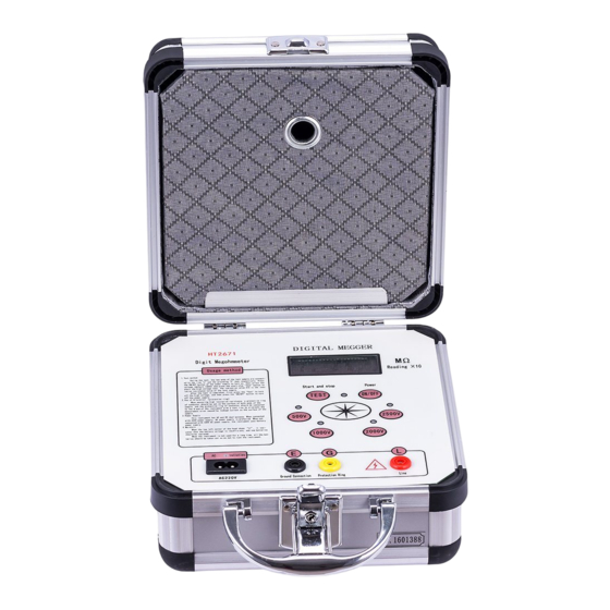
Thank you for Purchasing our HT2671 Insulation Resistance
Tester. Please read the manual in detail prior to first use, which will
help you use the equipment skillfully.
company's products continually, so there may be
slight differences between your purchase equipment
and its instruction manual. You can find the changes
in the appendix. Sorry for the inconvenience. If you have further
questions, welcome to contact with our service department.
may bring voltage, when you plug/draw the test wire or
power outlet, they will cause electric spark. PLEASE
CAUTION RISK OF ELECTRICAL SHOCK!
Company Address:
T4,No. 41, High-tech 2 Road,East Lake High-tech Development Zone,
Wuhan
Sales Hotline: 86-27- 87457960
After Service Hotline: 86-27- 87459656
Fax: 86-27- 87803129
E-mail: qiao@hvtest.cc
Website: www.hvtest.cc
Our aim is to improve and perfect the
The input/output terminals and the test column
1
Advertisement

Subscribe to Our Youtube Channel
Related Manuals for HVTest HT2671


Summary of Contents for HVTest HT2671
- Page 1 Dear Client Thank you for Purchasing our HT2671 Insulation Resistance Tester. Please read the manual in detail prior to first use, which will help you use the equipment skillfully. Our aim is to improve and perfect the company's products continually, so there may be slight differences between your purchase equipment and its instruction manual.
- Page 2 SERIOUS COMMITMENT All products of our company carry one year limited warranty from the date of shipment. If any such product proves defective during this warranty period we will maintain it for free. Meanwhile we implement lifetime service. Except otherwise agreed by contract.
- Page 3 shock, the grounding conductor must be connected to the ground. Make sure the product has been grounded correctly before connecting with the input/output port. Pay Attention to the Ratings of All Terminals To prevent the fire hazard or electric shock, please be care of all ratings and labels/marks of this product.
- Page 4 -Security Terms Warning: indicates that death or severe personal injury may result if proper precautions are not taken Caution: indicates that property damage may result if proper precautions are not taken.
-
Page 5: Table Of Contents
Contents I. Introduction·······························································6 II. Function and Features ················································ 7 III. Technique Specification············································· 8 IV. Operation Instructions··············································· 9 V. Notes ···································································· 10... -
Page 6: Introduction
I. Introduction 1. Principle of the meter HT2671 Digital Megger consists of medium and large scale integrated circuit with high output power and high short-circuit current value features. The output voltage is up to four grades. The built-in battery served as power supply become high DC voltage by DC/DC transformation, which goes from E pole to L pole via the object being tested. -
Page 7: Function And Features
energy sources. It is suitable for measuring the resistance of different kinds of insulating materials and insulation resistance of transformers, motors, cables and electrical equipment. II. Function and Features The meter has the following features: 1. High output power, strong load ability, and strong anti-interference ability. -
Page 8: Technique Specification
III. Technique Specification 1. Operating Conditions Temperature: 0℃~+45℃ Relative humidity: ≤85%RH 2. Output voltage grades, measuring range, resolution, error Output voltage grades: 500V,1000V,2000V,2500V Measuring range: 0~19990MΩ Resolution: 0.01MΩ,0.1MΩ,1.0MΩ,10.0MΩ Relative error: 0~2000MΩ≤±5%±2d, 2000MΩ~19990MΩ≤10%±2d 3. Load ability of maximum output voltage and short-circuit current Voltage/Load: 2500V/20MΩ... -
Page 9: Operation Instructions
IV. Operation Instructions 1. Measurement Procedure Turn the power switch “ON/OFF”, the default of meter is at 500V. Select the required voltage grade and the indicator light will show the selected voltage grade. Press the high voltage “start/stop” button and the indicator light for high voltage will glow. The stable value displaying on the LCD multiplied by 10 is the measured insulation resistance value. -
Page 10: Notes
the insulation resistance among components of electronic products, the “L” terminal and the “E” terminal can be connected to any line. When measuring the resistance between phases of electrical generator, you can choose two among the three phases at will, and the remaining one should be grounded. - Page 11 removed to prevent meters from corrosion.
Need help?
Do you have a question about the HT2671 and is the answer not in the manual?
Questions and answers