Advertisement
QUICK START GUIDE
FEATURES
• 1/3" 3.0 Megapixel CMOS Image Sensor
• Up to 30fps live view @ 3 MegaPixel (2048x1536)
• 2.8~12mm Varifocal Lens
• 30 Infrared LED's with 100' IR Range
• Digital Wide Dynamic Range (D-WDR)
• True Mechanical Day/Night function by ICR
• 3D-DNR Noise Reduction
• On Board Motion Detection, Privacy Masking, and ROI
• H.264 & MJPEG Compression
• Remote Viewing via CMS, Internet Explorer, and iOS &
Android Apps
• ONVIF Compliant
• IP66 Weather Resistance
• Optional Wall Mount (VT-TWM03) & Junction Box Mount
Available (VT-TJB02)
• Available in Ivory or Charcoal Gray
• 12VDC & PoE (Power over Ethernet) Operation
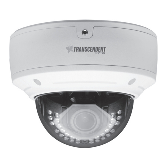
VTD-TND3RVE
Megapixel Indoor/Outdoor WDR
IP Dome Camera with 30 IR LED
PLEASE NOTE:
Complete User Guide, Software, Tools, and Updates are
available online. Scan the QR Code or visit:
http://www.vitekcctv.com/Downloads
Transcendent Series 3
Illumination
Advertisement
Table of Contents

Summary of Contents for Vitek VTD-TND3RVE
- Page 1 VTD-TND3RVE Transcendent Series 3 Megapixel Indoor/Outdoor WDR IP Dome Camera with 30 IR LED Illumination QUICK START GUIDE FEATURES • 1/3” 3.0 Megapixel CMOS Image Sensor • Up to 30fps live view @ 3 MegaPixel (2048x1536) • 2.8~12mm Varifocal Lens •...
- Page 2 Components and Accessories Camera Drill Template Quick Guide Rubber Gasket Screws Waterproof Cap Hex Wrench Overview RJ-45 Ethernet Power Cable...
- Page 3 Network Cable & Power Connections First connect the Waterproof Cap to an Ethernet patch cable, then connect the cameras ethernet adaptor. If not powering the camera with PoE, also connect the power Cable to an approved 12VDC Power Supply. Optional 12VDC Power Connection.
- Page 4 Installation Before beginning installation, make sure that the wall or ceiling is strong enough to withstand 3 times the weight of the camera. The mounting steps are as follows: 1. Loosen the screws to open the lower dome and then loosen the lock screw to remove Lock Screw the mounting base.
- Page 5 Installation 4. Install the camera to the mounting base with the lock screw. 5. Adjust the Three-axis camer Pan 0°~360° bracket to obtain the optimi- um viewing angle. Tilt 0°~75° Rotation 0°~360° 6. Adjust the Focus and Zoom screw to achieve a clear Zoom image.
- Page 6 LAN Configuration The camera can be accessed on the local network either using the IP-Tool or directly in a web browser. 1. Attach the drill template to the place where you want to install the camera, then drill 3 screw holes and 1 cable hole (if you want to route the cables through the mounting base) according to the drill template Accessing the Camera Using the IP-Tool...
- Page 7 4. Double-click the IP address and then the system will pop up the web browser to connect IP-CAM . IE browser will download the Active X control automatically. After downloading, a login window will pop up as shown below: Input the user name and password to log in. Default user name: admin / Default password: 123456.
- Page 8 2. Open the IE Browser and input the default address of IP-CAM and confirm. The IE browser will download Active X control automatical- Rubber Plug 3. After downloading Active X control, the login dialog box will pop up. 4. Input the default username and password and then enter to view. WAN Configuration Access the camera by the router or virtual server for example.


Need help?
Do you have a question about the VTD-TND3RVE and is the answer not in the manual?
Questions and answers