
Related Manuals for Texas Instruments Tiva TM4C1294


Summary of Contents for Texas Instruments Tiva TM4C1294
- Page 1 Tiva™ C Series TM4C1294 Connected LaunchPad Evaluation Kit EK-TM4C1294XL User's Guide Literature Number: SPMU365A March 2014 – Revised March 2014...
-
Page 2: Table Of Contents
............... References, PCB Layout, and Bill of Materials ........................References ..................... Component Locations ......................Bill of Materials ......................... Schematic ......................... Revision History Contents SPMU365A – March 2014 – Revised March 2014 Submit Documentation Feedback Copyright © 2014, Texas Instruments Incorporated... - Page 3 X11 Breadboard Adapter Even-Numbered Pad GPIO and Signal Muxing ................. 4-1. Connected LaunchPad Bill of Materials ......................6-1. Revision History SPMU365A – March 2014 – Revised March 2014 List of Figures Submit Documentation Feedback Copyright © 2014, Texas Instruments Incorporated...
-
Page 4: Board Overview
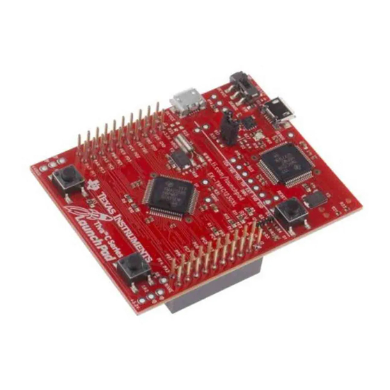
Figure 1-1 shows a photo of the Connected LaunchPad with key features highlighted. Figure 1-1. Tiva C Series Connected LaunchPad Evaluation Board Tiva is a trademark of Texas Instruments. All other trademarks are the property of their respective owners. Board Overview SPMU365A –... -
Page 5: Kit Contents
I/O brought to board edge for breadboard expansion • Two independent BoosterPack XL standard connectors featuring stackable headers to maximize expansion through BoosterPack ecosystem SPMU365A – March 2014 – Revised March 2014 Board Overview Submit Documentation Feedback Copyright © 2014, Texas Instruments Incorporated... -
Page 6: Boosterpacks
The Connected LaunchPad provides an easy and inexpensive way to develop applications with the TM4C1294NCPDTI microcontroller. BoosterPacks are add-on boards that follow a pin-out standard created by Texas Instruments. The TI and third-party ecosystem of BoosterPacks greatly expands the peripherals and potential applications that you can easily explore with the Connected LaunchPad. -
Page 7: Hardware Description
The quickstart application automatically connects to http://ti.exosite.com when an internet connection is provided through the RJ45 Ethernet jack on the evaluation board. SPMU365A – March 2014 – Revised March 2014 Hardware Description Submit Documentation Feedback Copyright © 2014, Texas Instruments Incorporated... -
Page 8: Ethernet Connectivity
PF0, which can be controlled by user’s software or the integrated Ethernet module of the microcontroller. A power LED is also provided to indicate that 3.3 volt power is present on the board. Hardware Description SPMU365A – March 2014 – Revised March 2014 Submit Documentation Feedback Copyright © 2014, Texas Instruments Incorporated... -
Page 9: Boosterpacks And Headers
U2CTS T4CCP1 USB0PFLT SSI2XDAT2 Analog U2Rx I2C6SCL T3CCP0 USB0EPEN SSI0XDAT2 EPI0S8 A out TMPR3 U0CTS T4CCP0 A out TMPR2 U0DCD T4CCP1 SPMU365A – March 2014 – Revised March 2014 Hardware Description Submit Documentation Feedback Copyright © 2014, Texas Instruments Incorporated... - Page 10 I2C7SDA T0CCP1 SSI2XDAT0 SPI MISO AIN15 I2C7SCL T0CCP0 SSI2XDAT1 GPIO U1DCD U2RTS EPI0S29 GPIO U1DSR U2CTS EPI0S30 GPIO U0DTR USB0NXT EPI0S29 Hardware Description SPMU365A – March 2014 – Revised March 2014 Submit Documentation Feedback Copyright © 2014, Texas Instruments Incorporated...
- Page 11 GPIO U3RTS U0DSR USB0D7 I2C SCL U1RI U3CTS I2C2SCL EPIO0S35 I2C SDA U1DTR U3RTS I2C2SDA EPIO0S34 Analog AIN10 U0CTS I2C5SCL SSI1Fss SPMU365A – March 2014 – Revised March 2014 Hardware Description Submit Documentation Feedback Copyright © 2014, Texas Instruments Incorporated...
- Page 12 SSI0Fss SPI MISO SSI3XDAT1 EPI0S23 U4Rx I2C8SCL T1CCP0 SSI0Clk GPIO U1CTS U0DCD USB0DIR EPI0S30 GPIO SSI3Fss EPI0S21 GPIO TMPR1 U0DSR T5CCP0 Hardware Description SPMU365A – March 2014 – Revised March 2014 Submit Documentation Feedback Copyright © 2014, Texas Instruments Incorporated...
-
Page 13: X11 Breadboard Adapter Odd-Numbered Pad Gpio And Signal Muxing
I2C6SDA T3CCP1 USB0PFLT USB0EPEN SSI0XDAT3 EPI0S9 I2C1SDA M0PWM5 EPI0S10 I2C1SCL EN0PPS M0PWM4 EPI0S11 T3CCP1 EPI0S12 T3CCP0 EPI0S13 T2CCP1 EPI0S14 T2CCP0 EPI0S15 SPMU365A – March 2014 – Revised March 2014 Hardware Description Submit Documentation Feedback Copyright © 2014, Texas Instruments Incorporated... - Page 14 USB0D5 EPI0S33 U1DTR U3RTS I2C2SDA EPI0S34 U1RI U3CTS I2C2SCL EPI0S35 U1RTS U1CTS U1DCD U2RTS EPI0S29 U1DSR U2CTS EPI0S30 U1Rx DIVSCLK WAKE Hardware Description SPMU365A – March 2014 – Revised March 2014 Submit Documentation Feedback Copyright © 2014, Texas Instruments Incorporated...
-
Page 15: X11 Breadboard Adapter Even-Numbered Pad Gpio And Signal Muxing
SSI1XDAT2 U6Tx SSI1XDAT3 USB0ID U1Rx I2C5SCL T4CCP0 CAN1Rx USB0VBUS U1Tx I2C5SDA T4CCP1 CAN1Tx EN0LED1 M0FAULT0 SSI3XDAT2 TRD3 EN0LED0 M0PWM0 SSI3XDAT1 TRD2 SPMU365A – March 2014 – Revised March 2014 Hardware Description Submit Documentation Feedback Copyright © 2014, Texas Instruments Incorporated... - Page 16 U3RTS U0DSR USB0D7 U3CTS I2C2SCL USB0D6 U3Rx U3Tx TMPR0 U0RI T5CCP1 TMPR1 U0DSR T5CCP0 TMPR2 U0DCD T4CCP1 TMPR3 U0CTS T4CCP0 RESET Hardware Description SPMU365A – March 2014 – Revised March 2014 Submit Documentation Feedback Copyright © 2014, Texas Instruments Incorporated...
-
Page 17: Power Management
USB host mode. This load switch also limits current to the BoosterPack and Breadboard adapter headers when the JP1 jumper is in the ICDI position. SPMU365A – March 2014 – Revised March 2014 Hardware Description Submit Documentation Feedback Copyright © 2014, Texas Instruments Incorporated... -
Page 18: Low Power Modes
R40 must be installed to use an external debug adapter to program or debug the Connected LaunchPad. Hardware Description SPMU365A – March 2014 – Revised March 2014 Submit Documentation Feedback Copyright © 2014, Texas Instruments Incorporated... -
Page 19: External Debugger
In the default configuration, UART0 maps to the virtual COM port of the ICDI. In the CAN jumper configuration, UART4 maps to the virtual COM port of the ICDI. SPMU365A – March 2014 – Revised March 2014 Hardware Description Submit Documentation Feedback Copyright © 2014, Texas Instruments Incorporated... -
Page 20: Software Development
Sourcery Codebench • Generic GNU C Compiler • Texas Instruments' Code Composer Studio™ IDE Download evaluation versions of these tools from the Tools & Software section of www.ti.com/tiva. Due to code size restrictions, the evaluation tools may not build all example programs. A full license is necessary to re-build or debug all examples. -
Page 21: Programming The Connected Launchpad
10. Set the Erase Method to Erase Necessary Pages, check the Verify After Program box, and check Reset MCU After Program. The example program starts execution once the verify process is complete. SPMU365A – March 2014 – Revised March 2014 Software Development Submit Documentation Feedback Copyright © 2014, Texas Instruments Incorporated... -
Page 22: References, Pcb Layout, And Bill Of Materials
LM Flash Programmer Tool (http://www.ti.com/lmflashprogrammer) • TPS73733 Low-Dropout Regulator with Reverse Current Protection (http://www.ti.com/product/tps79733) • Texas Instruments Code Composer Studio website (http://www.ti.com/ccs) • Tiva C Series TM4C1294NCPDT Microcontroller Data Sheet (http://www.ti.com/lit/gpn/tm4c1294ncpdt) • Build Your Own BoosterPack information regarding the BoosterPack standard (http://www.ti.com/byob) •... -
Page 23: Component Locations
Figure 4-1. Connected LaunchPad Dimensions and Component Locations SPMU365A – March 2014 – Revised March 2014 References, PCB Layout, and Bill of Materials Submit Documentation Feedback Copyright © 2014, Texas Instruments Incorporated... -
Page 24: Bill Of Materials
1/10W, 5%, 0402 R40, R41 Resistor, 330 ohm, R9, R27, R30, R31, R33 Yageo RC0402FR-07330RL 1/10W, 5%, 0402 References, PCB Layout, and Bill of Materials SPMU365A – March 2014 – Revised March 2014 Submit Documentation Feedback Copyright © 2014, Texas Instruments Incorporated... - Page 25 Right Angle Samtec TSW-149-09-F-S-RE extended, 1 x 49 0.100 pitch. valvano style breadboard X11B Samtec TSW-149-08-F-S-RA header. SPMU365A – March 2014 – Revised March 2014 References, PCB Layout, and Bill of Materials Submit Documentation Feedback Copyright © 2014, Texas Instruments Incorporated...
-
Page 26: Schematic
Microcontroller, USB, Buttons, and LED's • BoosterPack connectors • Breadboard connector • Ethernet and Ethernet LED's • Power • In-Circuit Debug Interface Schematic SPMU365A – March 2014 – Revised March 2014 Submit Documentation Feedback Copyright © 2014, Texas Instruments Incorporated... -
Page 27: Revision History
TARGET_VBUS/3.2C convienence test points for ground GPIO U7G$1 VBUS TP14 USBD_N U1G$1 P$33 P$95 TP15 USBD_P P$34 P$96 TARGET_VBUS/3.2C P$35 P$91 P$36 P$92 TARGET_ID P$37 P$121 TP16 P$38 P$120 P$40 P$41 TP17 P$100 3300pF TARGET_TCK/SWCLK/6.1A P$99 TARGET_TMS/SWDIO/6.1A USBD_N P$98 TPD4S012_DRY_6 TARGET_TDI/6.1E P$97 TARGET_TDO/SWO/6.1E... - Page 28 X8-2 TSW-110-02-S-D X8-1 X9-2 TSW-110-02-S-D GND/1.6B GND/1.6B X8-4 X9-1 X8-3 X9-3 X9-4 X8-5 X8-6 X9-5 X9-6 X8-7 X8-8 X9-7 X9-8 X8-9 X8-10 X9-9 TARGET_RESET/3.2D X9-10 0.1uF 0.1uF X8-11 X8-12 X9-11 X8-13 X8-14 X9-13 X9-12 X8-15 X8-16 X9-15 X9-14 X8-17 X8-18 X9-17 X9-16 X8-19...
- Page 29 This is the breadboard connection header. Samtec TSW-149-08-F-S-RA and TSW-149-09-F-S-RE can be used together to create a breadboard connector 0.1uF 0.1uF see the Users Manual for more information. TSW-149-02-S-D X11-2 X11-1 X11-4 X11-3 X11-6 X11-5 X11-8 X11-7 X11-10 X11-9 X11-12 X11-11 X11-14 X11-13...
- Page 30 Place pull up resistors and C16-C17 near TM4C MCU. MCU_3V3/5.2A 0.1uF 0.1uF Place C18 and C22 near pin 2 and pin 7 of U$10 P$16 P$16 EN0TXO_P/5.3B CHASSIS EN0TXO_N/5.3B P$14 P$14 P$15 P$15 TERM1A TERM1B P$11 P$11 TERM2A TERM2B CHASSIS EN0RXI_P/5.3B EN0RXI_N/5.3B P$10...
- Page 31 JP2 can be used to measure MCU current consumption with a multi-meter. WAKE MCU_3V3/4.1A SWITCH_TACTILE TP10 TP11 CRYATL_32K_SMD 12pF 12pF WAKE/3.3D Power Control Jumper: TARGET_RESET/3.2D U1G$2 1) To power from Debug install jumper on pins 5 - 6 P$66 P$65 XOSC0 R38 and C3 Used to meet 0.1uF...
- Page 32 Use this for JTAG IN from external debugger. See X1 JTAG PULL-UPS 5.6k jumpers for information about debug out to an DEBUG_VBUS/5.1B external target. MCU_3V3/5.6B TARGET_TCK/SWCLK/1.2A R40 must be removed for debug out. R40 must be instaled for debug in. TARGET_TMS/SWDIO/1.2B VTARGET DEBUG_PC1/TMS/SWDIO...
-
Page 33: Revision History
• Updated/Changed Pin 61 from "EPI0S12" to "GND" Table 2-4, X11 Breadboard Adapter Even-Numbered Pad GPIO and Signal Muxing: • Updated/Changed Pin 2 from "3V3" to "5V" SPMU365A – March 2014 – Revised March 2014 Revision History Submit Documentation Feedback Copyright © 2014, Texas Instruments Incorporated... - Page 34 IMPORTANT NOTICE Texas Instruments Incorporated and its subsidiaries (TI) reserve the right to make corrections, enhancements, improvements and other changes to its semiconductor products and services per JESD46, latest issue, and to discontinue any product or service per JESD48, latest issue.
Need help?
Do you have a question about the Tiva TM4C1294 and is the answer not in the manual?
Questions and answers