Table of Contents
Advertisement
Quick Links
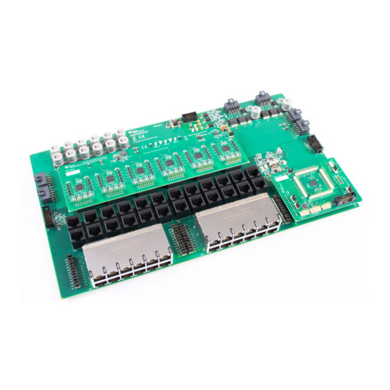
Design Guide: TIDA-050026-23881
24-Port (4 Pair) Power Sourcing Equipment Reference
Design for Multi-port Applications
Description
This reference design features an evaluation module
for the 24-port PSE system which contains a hardware
kit, a system firmware image, and a system firmware
GUI. The hardware kit consists of a motherboard
(PSEMTHR24EVM-081), an MSP430 daughtercard
(PSEMCUDAUEVM-082) and a PSE daughtercard
(TPS23881EVM-083). To evaluate the system (both
hardware and software), USB2ANY and MSP-FET
adapters are also needed.
NOTE: The MSP430F5234 on PSEMCUDAUEVM-082
are programmed with pre-production firmware for EVM
testing purposes. Follow the instructions in this user's
guide to flash the latest firmware from
evaluation.
Resources
Design Folder
TIDA-050026-23881
TPS23881EVM-083
Tool Folder
PSEMTHR24EVM-081
Tool Folder
PSEMCUDAUEVM-082
Tool Folder
TPS23881
Product Folder
MSP430F5234
Product Folder
CSD19538Q3A
Product Folder
ASK Our E2E™ Experts
Supply 1
Edge
Connector
_Power
Edge
Connector
_signal
SLVUBN3A – May 2019 – Revised October 2019
Submit Documentation Feedback
TI.com
before
Power
Power
Supply 2
USB2ANY Connector
PG1
PG2
Sensing
I2C Repeater
(Optional)
PSE Control Signals
Isolation
54 V to
PSE Daughter Card
PSE_3.3 V
Buck
PSE Ports
24-Port RJ45 Connectors
24-Port (4 Pair) Power Sourcing Equipment Reference Design for Multi-port
Copyright © 2019, Texas Instruments Incorporated
Features
•
Onboard power monitoring
•
24 4-pair port system, and expandable to 48 port
system
•
Highly flexible system with configurable GUI and
selectable host interface (I2C or UART)
•
Multiport power management
•
Multiple power supplies
•
Supports legacy powered devices (PDs)
Applications
•
Campus and branch switches
•
Edge router
•
Video recorder
54-V bus
PSE I2C bus
54 V to
GPIOs
ISO_3.3 V
MSP430
Isolated
DC/DC
I2C
UART SPI
GPIOs
USB2ANY Connector
PSE System Motherboard
Edge
Connector
_Power
Edge
Connector
_signal
MSP430
Daughter Card
JTAG
14 pin
Applications
1
Advertisement
Table of Contents

Related Manuals for Texas Instruments TIDA-050026-23881


Summary of Contents for Texas Instruments TIDA-050026-23881
- Page 1 DC/DC UART SPI GPIOs JTAG 24-Port RJ45 Connectors USB2ANY Connector 14 pin SLVUBN3A – May 2019 – Revised October 2019 24-Port (4 Pair) Power Sourcing Equipment Reference Design for Multi-port Applications Submit Documentation Feedback Copyright © 2019, Texas Instruments Incorporated...
-
Page 2: System Description
PSE system firmware GUI (request access through the TIDA-050026-23881 folder or the PSEMCUDAUEVM-082 tool folder) 24-Port (4 Pair) Power Sourcing Equipment Reference Design for Multi-port SLVUBN3A – May 2019 – Revised October 2019 Applications Submit Documentation Feedback Copyright © 2019, Texas Instruments Incorporated... -
Page 3: System Overview
EVM testing purposes. Follow the instructions in this user's guide to flash the latest firmware from the TIDA-050026-23881 folder or the PSEMCUDAUEVM-082 tool folder before evaluation. System Overview Block Diagram Figure 1. TIDA-050026-23881 Block Diagram PSE System Motherboard Power Power Supply 1 Supply 2 USB2ANY Connector Sensing... - Page 4 This is for hardware disable ports (reserved) GENERAL I/O P5.0 RESET PSE RESET Connect to PSE RESET pin 24-Port (4 Pair) Power Sourcing Equipment Reference Design for Multi-port SLVUBN3A – May 2019 – Revised October 2019 Applications Submit Documentation Feedback Copyright © 2019, Texas Instruments Incorporated...
- Page 5 PSE designs and enables interchangeable 2-layer PCB designs to accommodate different system PoE power configurations. SLVUBN3A – May 2019 – Revised October 2019 24-Port (4 Pair) Power Sourcing Equipment Reference Design for Multi-port Applications Submit Documentation Feedback Copyright © 2019, Texas Instruments Incorporated...
- Page 6 This 100-V, 49-mΩ, SON 3.3-mm × 3.3-mm NexFET™ power MOSFET is designed to minimize conduction losses and reduce the board footprint in PoE applications. 24-Port (4 Pair) Power Sourcing Equipment Reference Design for Multi-port SLVUBN3A – May 2019 – Revised October 2019 Applications Submit Documentation Feedback Copyright © 2019, Texas Instruments Incorporated...
- Page 7 10-mV full- scale. SLVUBN3A – May 2019 – Revised October 2019 24-Port (4 Pair) Power Sourcing Equipment Reference Design for Multi-port Applications Submit Documentation Feedback Copyright © 2019, Texas Instruments Incorporated...
-
Page 8: Required Hardware And Software
FirmPSE GUI (request access to the GUI through the TIDA-050026-23881 folder or the PSEMCUDAUEVM-082 tool folder) 24-Port (4 Pair) Power Sourcing Equipment Reference Design for Multi-port SLVUBN3A – May 2019 – Revised October 2019 Applications Submit Documentation Feedback Copyright © 2019, Texas Instruments Incorporated... -
Page 9: Test Setup
NOTE: A 30-pin ribbon cable is required to enable the full features of PSE system firmware GUI. SLVUBN3A – May 2019 – Revised October 2019 24-Port (4 Pair) Power Sourcing Equipment Reference Design for Multi-port Applications Submit Documentation Feedback Copyright © 2019, Texas Instruments Incorporated... - Page 10 I2C data from or to PSE TP17 PSE_SCL I2C clock to PSE 24-Port (4 Pair) Power Sourcing Equipment Reference Design for Multi-port SLVUBN3A – May 2019 – Revised October 2019 Applications Submit Documentation Feedback Copyright © 2019, Texas Instruments Incorporated...
- Page 11 USB2ANY connector (30 pin) J17, J18 For MSP430 daughtercard mechanical mounting purpose SLVUBN3A – May 2019 – Revised October 2019 24-Port (4 Pair) Power Sourcing Equipment Reference Design for Multi-port Applications Submit Documentation Feedback Copyright © 2019, Texas Instruments Incorporated...
- Page 12 Offline mode is selected by default. Figure 3. GUI Startup 24-Port (4 Pair) Power Sourcing Equipment Reference Design for Multi-port SLVUBN3A – May 2019 – Revised October 2019 Applications Submit Documentation Feedback Copyright © 2019, Texas Instruments Incorporated...
- Page 13 PD is removed from the port and reconnects to the port. SLVUBN3A – May 2019 – Revised October 2019 24-Port (4 Pair) Power Sourcing Equipment Reference Design for Multi-port Applications Submit Documentation Feedback Copyright © 2019, Texas Instruments Incorporated...
- Page 14 It allocates the unused power of the port to other ports. 24-Port (4 Pair) Power Sourcing Equipment Reference Design for Multi-port SLVUBN3A – May 2019 – Revised October 2019 Applications Submit Documentation Feedback Copyright © 2019, Texas Instruments Incorporated...
- Page 15 5–8) can be mapped to one 4-pair port. Figure 6. GUI Device Configuration SLVUBN3A – May 2019 – Revised October 2019 24-Port (4 Pair) Power Sourcing Equipment Reference Design for Multi-port Applications Submit Documentation Feedback Copyright © 2019, Texas Instruments Incorporated...
- Page 16 MSP430 device directly. Figure 8. GUI Configuration Summary 24-Port (4 Pair) Power Sourcing Equipment Reference Design for Multi-port SLVUBN3A – May 2019 – Revised October 2019 Applications Submit Documentation Feedback Copyright © 2019, Texas Instruments Incorporated...
- Page 17 PC and the GUI is in online mode after selecting the host interface protocol. Figure 10. Host Interface Protocol Selection in Online Mode SLVUBN3A – May 2019 – Revised October 2019 24-Port (4 Pair) Power Sourcing Equipment Reference Design for Multi-port Applications Submit Documentation Feedback Copyright © 2019, Texas Instruments Incorporated...
- Page 18 I2C or UART port as the normal communication. This is beneficial to firmware upgrade after the product is released to customers. 24-Port (4 Pair) Power Sourcing Equipment Reference Design for Multi-port SLVUBN3A – May 2019 – Revised October 2019 Applications Submit Documentation Feedback Copyright © 2019, Texas Instruments Incorporated...
- Page 19 1. Select the MCU device to MSP430F5234 Figure 13. MCU Device Selection Page SLVUBN3A – May 2019 – Revised October 2019 24-Port (4 Pair) Power Sourcing Equipment Reference Design for Multi-port Applications Submit Documentation Feedback Copyright © 2019, Texas Instruments Incorporated...
- Page 20 3. Load BSL code and flash to the MSP430 MCU. Figure 15. Select and Load Images Page 24-Port (4 Pair) Power Sourcing Equipment Reference Design for Multi-port SLVUBN3A – May 2019 – Revised October 2019 Applications Submit Documentation Feedback Copyright © 2019, Texas Instruments Incorporated...
- Page 21 The IEEE 802.3bt compliance test suite is not available now. The test report will be added once available. SLVUBN3A – May 2019 – Revised October 2019 24-Port (4 Pair) Power Sourcing Equipment Reference Design for Multi-port Applications Submit Documentation Feedback Copyright © 2019, Texas Instruments Incorporated...
- Page 22 To download the schematics, see the design files at TIDA-050026-23881. Bill of Materials To download the bill of materials (BOM), see the design files at TIDA-050026-23881. PCB Layout Recommendations KSENSA is shared between SEN1 and SEN2, KSENSB is shared between SEN3 and SEN4, KSENSEC is shared between SEN5 and SEN6, KSENSED is shared between SEN7 and SEN8.
-
Page 23: Revision History
Revision History Changes from Original (May 2019) to A Revision ......................Page ................• The SLVUBN3 is completely reworked in revision A. SLVUBN3A – May 2019 – Revised October 2019 Revision History Submit Documentation Feedback Copyright © 2019, Texas Instruments Incorporated... - Page 24 TI products. TI’s provision of these resources does not expand or otherwise alter TI’s applicable warranties or warranty disclaimers for TI products. Mailing Address: Texas Instruments, Post Office Box 655303, Dallas, Texas 75265 Copyright © 2019, Texas Instruments Incorporated...
Need help?
Do you have a question about the TIDA-050026-23881 and is the answer not in the manual?
Questions and answers