
Related Manuals for Texas Instruments TI CC3000 BoosterPack


Summary of Contents for Texas Instruments TI CC3000 BoosterPack
- Page 1 TI CC3000 BoosterPack Evaluation Board User's Guide Literature Number: SWRU331 November 2012...
-
Page 2: Table Of Contents
Bill of Materials (BOM) ..................2.6.1 PCB Design Guidelines ......................2.6.2 RF Trace ......................2.6.3 Antenna ....................... 2.6.4 Power Trace ......................2.6.5 Ground ....................Application Development Contents SWRU331 – November 2012 Submit Documentation Feedback Copyright © 2012, Texas Instruments Incorporated... - Page 3 Header J10 of the CC3000 BoosterPack Board Bottom View ................2-7. Launchpad to BoosterPack Pin Comparison ....................... 2-8. PCB Stack-Up Data ..................2-9. Trace Design Measurement Values SWRU331 – November 2012 List of Figures Submit Documentation Feedback Copyright © 2012, Texas Instruments Incorporated...
-
Page 4: Preface
Preface SWRU331 – November 2012 Read This First About This Manual This user guide describes how to use the TI CC3000 BoosterPack evaluation board to evaluate the performance of the TI CC3000 module. Related Documentation From Texas Instruments • TI SimpleLink™ CC3000 Module – Wi-Fi 802.11b/g Network Processor Data Sheet (SWRS126) •... -
Page 5: Introduction
Chapter 1 SWRU331 – November 2012 Introduction This user guide describes how to use the TI CC3000 BoosterPack evaluation board to evaluate the performance and functionality of the TI CC3000 module. The TI CC3000 module is a self-contained Wi-Fi ®... -
Page 6: Cc3000 Boosterpack Evaluation Board
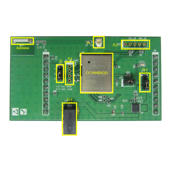
Connect pins 1 and 2 for power from the LaunchPad flash programmer and debugging tool. Connect pins 2 and 3 for external power. CC3000 BoosterPack Evaluation Board SWRU331 – November 2012 Submit Documentation Feedback Copyright © 2012, Texas Instruments Incorporated... -
Page 7: Cc3000 Boosterpack Board Bottom View
The two BoosterPack mating connectors (J9 and J10) connect to the host platform and mount to the bottom of the BoosterPack board, as shown in Figure 2-2. Table 2-5 Table 2-6 describe the signals on J9 and J10. SWRU331 – November 2012 CC3000 BoosterPack Evaluation Board Submit Documentation Feedback Copyright © 2012, Texas Instruments Incorporated... -
Page 8: Cc3000 Boosterpack Board Bottom View
Descriptions – Ground WL_SPI_IRQ Output Host interface SPI interrupt request WL_SPI_CS Input Host interface SPI chip select Reserved – Reserved Reserved – Reserved CC3000 BoosterPack Evaluation Board SWRU331 – November 2012 Submit Documentation Feedback Copyright © 2012, Texas Instruments Incorporated... -
Page 9: Antenna
Figure 2-3 shows the matching circuit between the antenna and the BoosterPack board. AT8010-E2R9HAA SWRU331-003 Figure 2-3. Antenna Location and RF Trace Routing SWRU331 – November 2012 CC3000 BoosterPack Evaluation Board Submit Documentation Feedback Copyright © 2012, Texas Instruments Incorporated... -
Page 10: Matching Circuit Between The Antenna And The Cc3000 Boosterpack
Figure 2-4. Matching Circuit Between the Antenna and the CC3000 BoosterPack The return loss is based on the matching circuit and RF trace routing, as shown in Figure 2-5. CC3000 BoosterPack Evaluation Board SWRU331 – November 2012 Submit Documentation Feedback Copyright © 2012, Texas Instruments Incorporated... -
Page 11: Return Loss From The Acx Antenna And Matching Circuit
Antenna www.ti.com SWRU331-005 Figure 2-5. Return Loss From the ACX Antenna and Matching Circuit SWRU331 – November 2012 CC3000 BoosterPack Evaluation Board Submit Documentation Feedback Copyright © 2012, Texas Instruments Incorporated... -
Page 12: Antenna Radiation Pattern
Antenna www.ti.com SWRU331-006 Figure 2-6. Antenna Radiation Pattern CC3000 BoosterPack Evaluation Board SWRU331 – November 2012 Submit Documentation Feedback Copyright © 2012, Texas Instruments Incorporated... -
Page 13: Hardware Setup
VBAT_IN P1.0 VBAT_SW_EN P1.1/TX 1.2/RX P1.3 P1.4 P1.5 WL_SPI_CLK P2.0 P2.1 P2.2 P2.3 P2.4 P2.5 P1.6 WL_SPI_DOUT P1.7 WL_SPI_DIN T/SBWT T/SBW 2.6/XOUT WL_SPI_CS SWRU331 – November 2012 CC3000 BoosterPack Evaluation Board Submit Documentation Feedback Copyright © 2012, Texas Instruments Incorporated... - Page 14 Hardware Setup www.ti.com Table 2-7. Launchpad to BoosterPack Pin Comparison (continued) MSP430 Port CC3000 BoosterPack P2.7/XIN WL_SPI_IRQ CC3000 BoosterPack Evaluation Board SWRU331 – November 2012 Submit Documentation Feedback Copyright © 2012, Texas Instruments Incorporated...
-
Page 15: Cc3000 Boosterpack Schematic
CC3000 BoosterPack Schematic www.ti.com CC3000 BoosterPack Schematic Figure 2-8 shows the CC3000 BoosterPack schematics. Figure 2-8. CC3000 BoosterPack Schematics SWRU331 – November 2012 CC3000 BoosterPack Evaluation Board Submit Documentation Feedback Copyright © 2012, Texas Instruments Incorporated... -
Page 16: Bill Of Materials (Bom)
Figure 2-9. Trace Design for PCB Layout Table 2-9. Trace Design Measurement Values Measurement Length H (height between L1 and L2) 52.2 mil H1 (height 1) 0.5 mil CC3000 BoosterPack Evaluation Board SWRU331 – November 2012 Submit Documentation Feedback Copyright © 2012, Texas Instruments Incorporated... -
Page 17: Antenna
2.6.4 Power Trace Figure 2-11 shows the power trace for VBAT_IN highlighted in white. NOTE: VBAT_IN must have a thickness of 24 mil or more. SWRU331 – November 2012 CC3000 BoosterPack Evaluation Board Submit Documentation Feedback Copyright © 2012, Texas Instruments Incorporated... -
Page 18: Ground
Ground vias must be close to the pad. Figure 2-12 shows the ground routing for the CC3000 BoosterPack board. SWRU331-012 Figure 2-12. Ground Routing for the CC3000 BoosterPack Board CC3000 BoosterPack Evaluation Board SWRU331 – November 2012 Submit Documentation Feedback Copyright © 2012, Texas Instruments Incorporated... -
Page 19: Application Development
Launchpad MSP-EXP430G2 test platform and the CC3000 BoosterPack board. SWRU331-013 Figure 3-1. MSP-EXP430G2 Test Platform and CC3000 BoosterPack Board To order the MSP-EXP430G2 test platform, go to the following link: http://www.ti.com/tool/msp-exp430g2 SWRU331 – November 2012 Application Development Submit Documentation Feedback Copyright © 2012, Texas Instruments Incorporated... - Page 20 IMPORTANT NOTICE Texas Instruments Incorporated and its subsidiaries (TI) reserve the right to make corrections, enhancements, improvements and other changes to its semiconductor products and services per JESD46, latest issue, and to discontinue any product or service per JESD48, latest issue.
Need help?
Do you have a question about the TI CC3000 BoosterPack and is the answer not in the manual?
Questions and answers